The CF arrived. I think I got lucky and guessed correctly at tube sizes for my purposes (as I could not find the deflection information I would have needed to make a more educated guess.)
The surprise came with the bias web CF material. I bought it to laminate into braces. Now I'm thinking of also using it as neck reinforcement.
Using my right brain method of simply holding the material and trying to flex it, I am convinced that the bias web is much stiffer than the pultruded rods I had purchased from Los Alamos Composites. (Nothing wrong with the Los Alamos stuff, and it will get used in other guitar necks.)
I have been working on CAD drawings for a baritone scale length guitar, and realized that the commonly found 18" length of CF rectangular rods for guitar neck reinforcement are too short for a baritone (especially with a cantilevered fingerboard.) I need about 22" if the CF goes through the headstock.
With the stiffness of the .030" thick x .375" shear web material, I figure I can cut 1/16" grooves (one on each side of a trussrod channel) with a tablesaw and a Freud Diablo thin kerf blade, and epoxy in 2 pieces of the .030" into each slot. I'm confident (after my not very scientific "testing") that this will actually be stronger than using .125" x .375" rectangular pultruded rods. About half the price, stronger (or so I believe), and sufficient length to do longer necks.
Dennis
Graphite Required Urgently (A Graphite Discussion ;-)
-
Dennis Leahy

- Blackwood
- Posts: 872
- Joined: Wed Oct 10, 2007 12:32 am
- Location: Duluth, MN, US
- Contact:
I very much doubt that you will have comparable strength or stiffness Dennis.
Unless the quality of the Carbon fibres themselves is far superior, you have halved the crossectional area and at the same time placed the fibres in a less favorable orientation for bending which takes off another 50% or so.
Think of it this way. If you had timber with 45 degree runout would you cut it into strips and laminate it in different directions and use it for a neck, or would you just find some straight grain timber.
It is not easy to assess material stiffness by hand especially thin materials parallel to the major dimension.
-
Dennis Leahy
- Blackwood
- Posts: 872
- Joined: Wed Oct 10, 2007 12:32 am
- Location: Duluth, MN, US
- Contact:
Jeff, you may be correct, and it was admittedly a meager seat-of-the-pants "test."jeffhigh wrote:I very much doubt that you will have comparable strength or stiffness Dennis.
Unless the quality of the Carbon fibres themselves is far superior, you have halved the crossectional area and at the same time placed the fibres in a less favorable orientation for bending which takes off another 50% or so.
Think of it this way. If you had timber with 45 degree runout would you cut it into strips and laminate it in different directions and use it for a neck, or would you just find some straight grain timber.
It is not easy to assess material stiffness by hand especially thin materials parallel to the major dimension.
However, as for the ideal direction of the fibers, here is my right brained logic (oxymoronic, I know):
If I was making a monopod (one-legged variant of a tripod), I think the pultruded rod with all the fibers oriented along the length would be perfect. I would expect the pultruded rods to have the highest compressive strength. If I was making archery bows, I would also think of pultruded rods, but for a different reason: because (if the correct size was selected), it would bend gaining a lot of potential energy, and when released would want to straighten out. If I was making an all-wood laminated bow, I'd laminate layers of wood perpendicular to the shaft of the arrow, so the bow could bend. If left strung-up for a long while, I'd think perhaps the all-wood bow might not ever return to exactly the same position as it was before ever having been strung. If I wanted to ensure that it would be able to return closer to exactly the same as it was before being strung, I would think of laminating a layer of CF in with the wood.
If I wanted to make a bow that was nearly impossible to bend, I would think of running the wood layers and the CF in the same plane as the arrow. (beam strength) So far, I would expect we are in agreement. Now, I think our only disagreement is which way the fibers in the beam should run for maximum resistance to the neck bending. My thought is that the 160 to 200 pounds of string force is not acting as a compressive force on the neck, because the strings are a distance away from the central core of the neck. Well, of course, the compressive force is there too, but that is not what distorts the neck. The neck distortion comes from a torque force from the neck having the load offset, actually quite similar to an archery bow. So, that's why I'm thinking that the compressive strength of the CF rod really does not even come into play and the ideal material would resist the torque force generated by the strings that are trying to bow the fingerboard forward.
We know that literally millions of guitars have been built without any CF at all in their necks and many survive a lifetime of playing - some with a counter force applied by a truss rod. It's probably true to say that any CF, in any orientation, will improve the neck's resistance to bowing to some degree. So, I don't think I'm courting disaster by using four 1/32" x 3/8" bias web pieces of CF rather than two 1/8" x 3/8" pultruded rectangles. I'd welcome some info to prove or disprove my notion (and really, that's about all it is) that the bias web material is stronger against the torque force than the pultruded rod material. From my simple flexing of the material, I'd be willing to bet a Vegemite sandwich that the bias web material is not only stronger against torque, but that it is at least twice as strong. Maybe David Hurd has some data?
Dennis
Another damn Yank!
-
Paul B
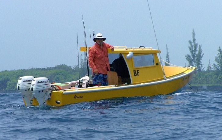
Nice boat Dave!hilo_kawika wrote:Aloha Dennis,
I'm a big fan of the 45 degree layed up sheets for bridge plates. I think I had a brief tutorial about it here somewhere. And I agree that using it flat or on edge would be quite useful - especially on edge where the fibers would always be in tension. And the folks at the composites store have always been good to deal with as well.
When I built my 18' long fishing boat using the stitch-n-glue method I used a triple overlap of biaxial woven roving on each seam inside and out for the same reason - fibers would always be in tension during any possible flexing. The boat's pretty stiff I must say. Here I am at the helm with a friend along for fishing yesterday:
aloha,
Dave Hurd
http://www.ukuleles.com
I was into building kayaks for several years, want to build a fishing boat, but guitars are so much easier to move around the the shop.
Funny thing is that there are a quite a few guitar builders that started out on boats. That's were I met Grant Goltz for the first time (what 12 years ago? sheesh) - building boats.
The missus is going to be real surprised when I drag a 24' Tolman skiff out of the shop.
Hi Dennis,
Happy to discuss this more.
First the terms you are using-Torque is wrong for this application
Torque is a twisting force.
The tension of the strings above the fretboard induces a compressive load in the fingerboard and the surface below it and a tensile force in the rear of the neck.
This means the neck is in bending and compression.
Any additional reinforcement that you BOND into the neck will have its top and bottom extreme fibres acting in compression and tension.
Parallel fibres are the most efficient in tension here, 45 degree fibres present a discontinuity.
So it is important to get as much crossectional area of the reinforcemt as possible towards the back of the neck.
Hope this makes sense to you.
regards
Jeff
-
Dennis Leahy
- Blackwood
- Posts: 872
- Joined: Wed Oct 10, 2007 12:32 am
- Location: Duluth, MN, US
- Contact:
Yeah, I had a feeling that saying "torque" is wrong, and wish I had spent some time to even learn the correct names for the force vectors. Interesting that at one end of the string (the bridge) we speak of torque forces and can visualize them when we see a bellied guitar. Would it still be torque force if the bridge was 3" wide instead of 1-1/2"? Or what if the bridge was 2" x 18" and stuck onto the top longitudinally. We certainly wouldn't see the soundboard belly, but would the top still be experiencing a torque force?
(I know I'm stretching a bit here but) what if you connected a torque wrench on the neck right under the nut and twisted it forward. Isn't that kinda the same thing that the strings are doing?
I can visualize the I-beam concept, where the top platform of the beam in under compression and the bottom platform of the beam is in tension. But, when I physically bend the rectangular pultruded rod compared to the shear web, the web seems to make a stiffer beam.
Jeff, what's your take on the 45° laminated shear web material - what use do you see for it in lutherie? Do you think the unidirectional sheet or the alternating 45° shear web make more sense in braces (assuming I want the CF primarily to help my braces to retain their original radius *forever*.)
Thanks!
Dennis
Another damn Yank!
[
Jeff, what's your take on the 45° laminated shear web material - what use do you see for it in lutherie? Do you think the unidirectional sheet or the alternating 45° shear web make more sense in braces (assuming I want the CF primarily to help my braces to retain their original radius *forever*.)
I thinks David's usage of 45deg CF for bridgeplates sounds like a great idea.
Not too sure where else I would use it.
For laminated bracing you would certainly want the unidirectional material, but i am not really convinced of the need for it in most situations.
Jeff,jeffhigh wrote:
I thinks David's usage of 45deg CF for bridgeplates sounds like a great idea.
Not too sure where else I would use it.
For laminated bracing you would certainly want the unidirectional material, but i am not really convinced of the need for it in most situations.
I sort of get this but could you please elaborate 'why' 45deg CF is a great idea for bridge plates and 'why' you would certainly want unidirectional CF for laminating into bracing?
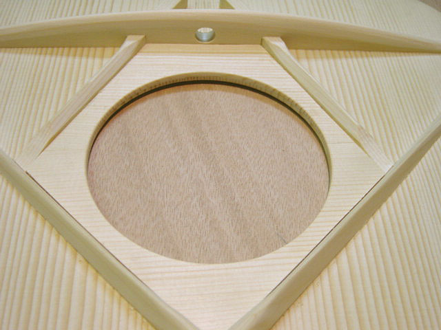
Also by laminating, I assume you are referring to vertical lamination and if this is indeed the case, and one did want to create an 'unmovable' upper transverse brace, then would the design represented in my rather crude 'cross section' image be a good one having the series of vertical laminations using vertical grain spruce and unidirectional CF (represented by the 3 green lines) and the bottom or the brace being capped with strip of horizontal 45 deg stock as represented by the red line.
Have I got this right? If not, what would you recommend?
I ask because my most recent project has forced me to really think about this and since doing so I certainly do see a very valid use for CF in the upper transverse brace, probably even more valid there IMO than in the neck.
To explain so everyone will hopefully understand my point, I offer the following.
We all know that with the passage of time it is common for a steel string bridge to roll as a direct result of the compressive force that you mentioned above.
In order for this 'roll' to take place, the soundboard behind the bridge must also rise or 'bellie' upward as a result of 'tensile' force and with rotation, that area in front of the bridge, between it and the soundhole, must concave or bellie downward as a result of compressive force with the whole process resulting in the formation of a cross sectional horizontal "S" shape being formed when viewing the bridge and top from the side across the top's surface.
As this rotation takes place, the action, or distance between the stings and the fretboard begins to rises and so too does the relevance of Dennis's analogy with the long bow. The wood at the back of the bridge can only offer so much movement before it resist the tensile force of the strings. At this point, the glue joint at the bridge will either let go, or the compressional force now applying increased 'leverage' at the neck joint will force the neck to rise and continue to magnify the problem.
With each rise, more force is given over to pulling the headstock 'up' to meet the bridge and less is available to pulling the neck 'in' toward the neck block as one would expect in a newly set up guitar. This results in more and more pressure being placed upon the neck block and upper transverse brace as these components become a fulcrum point with the neck the lever.
The more the guitar folds with this rotation around the neck block, the more quickly it will continue to fold as the soundboard either side of the fretboard extension eventually break free and allow the neck block to rotate back into the guitar body completing the failure with the collapse of the upper transverse brace.
Like most of us, I look at the guitar as a complete unit. The initial failure back at the bridge can be addressed somewhat IMO by correctly bracing to counteract the torque to limit the 'rolling' of the bridge in the first instance. In my right brained way this includes a doubling up of the top thickness around the soundhole by laying in a plate of apposing grain spruce to be bordered by the "A" frame soundhole braces the front intersection of the "X" brace and the rear edge of the UTB and with my current thinking, this area now becomes a prime candidate for 45 deg CF instead of the spruce or may be in conjunction with it.
(I will now be moving to truss rod access at the headstock so please ignore the big hole in the transverse.)
Anyhow, I also think stiffening up the sides as per Rick Turner CF reinforced linings will help prevent the neck block rotation issue as would flying buttress CF tubes running from the neck block back to the waist as installed by the brilliant Dave White, and to complete the system and insert the point of my long winded post, so too would a super strength upper transverse brace that had been laid up with CF.
I feel that if you get things right here, your covered structurally and this frees you up to brace much lighter at the lower bout where it counts. My2c. However, as with all things I remain open and am enjoying the education this topic has provided.
Cheers all.
Kim
Kim,
The 45deg stuff would be good for bridgeplates to resist splitting across the grain and distribulte load in both directions.
In terms of your diagram,for the UTB I would skip the vertical laminations and cap the brace with unidirectional CF not 45 degree.
I like the gentle curve of the UTB shown in your photo and if you carry that curve all the way to the linings and cap it with CF all the way (not scalloping the ends) you will have a very strong brace indeed.
I would not be worried about the hole in the centre of the brace, you have plenty of "meat" below it.
IMHO the main factor in avoiding dipping at the soundhole is capping the x brace intersection properly rather than with a bit of muslin like CF Martin.(as well as adequate brace height and avoiding cutting away too much in shaping)
IMHO you have already taken the main step to avoiding neck block rotation by using the A brace to the neck block. Adding flying buttresses etc is only doubling up on this and attempting to transfer load to the sides(from where it has to then be transferred back to the top and across to the bridge)
I am not convinced that it is necessary or desirable to try to transfer loads out of the top, but you do need to distribute them to the areas beside the soundhole and the A bracing does that
I remain unconvinced about the benefits of CF capped linings, I look at it this way- the top is an extremely effective brace for the sides (and vice versa)
Thanks Jeff, and no disrespect intended, but I am not really any wiser because you have still not elaborated on 'why' you are suggesting what you do.
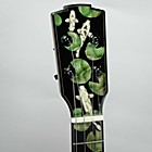
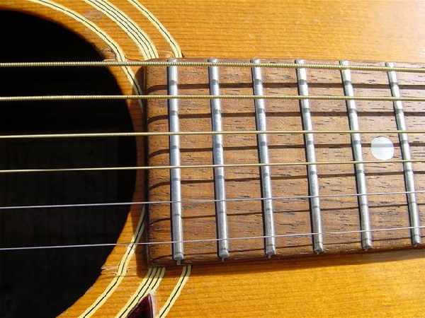
Here is one I done, the distortion of the rosette clearly shows how much the top around the fretboard extension has moved after cracking, the X and capping on this particular guitar was just fine.
One thing I will be doing in the future is to laminate CF sheet stock between the top and the soundhole patch. If it can work back at the bridge plate, I reckon it will be equally effective around the soundhole which is and area I consider to be the weakest link in the traditionally 'X' braced top. Add some CF and overlay with a veneer of cheesewood and you have a neat purfling on the inside edge of the soundhole, chique.
Cheers
Kim
I won't argue with you because you are an engineer, but how does it do this?jeffhigh wrote:
The 45deg stuff would be good for bridgeplates to resist splitting across the grain and distribulte load in both directions.
Once again I am sure your advice has great merit but I have no understanding of 'why' you have suggested this.jeffhigh wrote: In terms of your diagram,for the UTB I would skip the vertical laminations and cap the brace with unidirectional CF not 45 degree.
Sorry Jeff but I can't agree with that statement because I have had to repair a few steel strings now, both cloth and spruce capped, that have bellied the back of the bridge, caved in the soundboard at the rear of the soundhole, and rotated the front and sides of the upper bout and neck block back into the guitar so far that the FB extension has crack the top either side on it's way into the body. All examples have been relatively over braced factory guitars, and on all but one of these, the "X" brace and capping had remained completely undisturbed.jeffhigh wrote: IMHO the main factor in avoiding dipping at the soundhole is capping the x brace intersection properly rather than with a bit of muslin like CF Martin.(as well as adequate brace height and avoiding cutting away too much in shaping)
Here is one I done, the distortion of the rosette clearly shows how much the top around the fretboard extension has moved after cracking, the X and capping on this particular guitar was just fine.
Granted, but my experience fixing those that have failed has clearly demonstrated to me that the top to side relationship is not an effective enough brace to be relied upon to avoid rotation over the long term for many steel string acoustic guitars. This is why I would like to know more about which CF product should be use in what application. But more importantly, I would like to understand 'why' one is more effective than the other so it adds another quiver to the quill as I continue to work my way through the craft.jeffhigh wrote: I remain unconvinced about the benefits of CF capped linings, I look at it this way- the top is an extremely effective brace for the sides (and vice versa)
One thing I will be doing in the future is to laminate CF sheet stock between the top and the soundhole patch. If it can work back at the bridge plate, I reckon it will be equally effective around the soundhole which is and area I consider to be the weakest link in the traditionally 'X' braced top. Add some CF and overlay with a veneer of cheesewood and you have a neat purfling on the inside edge of the soundhole, chique.
Cheers
Kim
-
Dennis Leahy
- Blackwood
- Posts: 872
- Joined: Wed Oct 10, 2007 12:32 am
- Location: Duluth, MN, US
- Contact:
...and, I thought I had made a great discovery that the 45° bias web material would actually bend less as a beam than pultruded rod or unidirectional sheet material. Damn engineers! 
Well, I suppose I should buy an elementary book on engineering, so at least I'd know the proper terminology for the force vectors. Especially considering that I have an experimental nature and have already abandoned the X-brace as a model to emulate.
So Jeff, like Kim, I will lay out the big picture of what I'm trying to do, in the hope that I might take advantage of your engineering expertise.
1.) Neck reinforcement. I suspect that I have been "fooled by my fingers" into believing the bias web (45°) layered composite is stronger than unidirectional fibers, used as a beam, in a guitar neck. So much for my cost savings, as about $22 worth of that material in in the post to me now, and now I don't know what purpose it will serve. But I digress.
One problem I see with the typical CF used in necks is the .375" dimension. That puts the bottom of the dado channel dangerously close to being exposed at the back of the neck, and makes thin necks impossible. I know some luthiers are following Rick Turner's lead and inletting part of the .375" into the backside (bottom) of the fingerboard, but at this point, I'm not so sure I like that solution.
The neck designs I'm considering will be adjustable and will have cantilevered fingerboard extensions. I'm also working on a design for an 8-string baritone guitar, and that one will certainly benefit from anything that is done to stiffen the extra long neck. So, I "need" CF to be about 20" long or about 22" long if the CF goes through the head (easier to build and probably stronger.)
So, now that the bias web material idea is shite, I'm looking at T723-4 rectangular rod (0.125" x 0.325" x 48") which is long enough to cut a pair of CF rods for even the long neck (and, at $11.15 each 48" strip, that makes the price of rods about $5.60 each.) I know that the .325" dimension will reduce the stiffness compared to .375" material, but it has the benefit of a slightly shallower dado channel.
2.) Brace reinforcement. The only guitar I've built so far has suspended bracing from neck block to tail block, and there is really only one brace on the soundboard holding the arch/radius of the top. I have a single lateral brace running across the guitar right beneath the saddle. The concept is that this brace is a fulcrum, allowing the bridge to rock longitudinally. Based on the success of that guitar, I'm continuing to experiment along that pathway.
The idea with using CF laminated into this "pivot brace", is to create a thin brace that will hold the radius machined into it, permanently. Whereas most guitars have several radiused braces assisting in the task of maintaining the top's radius, if my one brace relaxes a bit after a few years, I could lose most of the top's arch. I suspect that you'd recommend a capped brace (capped with CF) or some variant of I-beam construction, but I am hoping to simplify the process and just laminate a thin sheet of CF between spruce for this brace. Is that simple, laminated concept going to achieve the goal (of remaining as it's machined arch) or do I have to look at capping the brace to achieve it?
Thanks in advance for your assistance!
Dennis
{edit}Added cross section image.

Cross Section at Pivot Brace
Here are my thoughts if it needs to be capped on top and bottom - full I-beam. The bottom cap would be straight/flat and easier to make. The top cap would be curved to the desired top radius, and would be a bit trickier to achieve - I'd leave it out if it is really not doing much to stiffen the brace.
If it only needs a bottom cap, then maybe omit the wood veneer layers, and just use the CF, epoxied on. In fact, maybe that's better, as it epoxies the vertical and horizontal members touching CF to CF.
Well, I suppose I should buy an elementary book on engineering, so at least I'd know the proper terminology for the force vectors. Especially considering that I have an experimental nature and have already abandoned the X-brace as a model to emulate.
So Jeff, like Kim, I will lay out the big picture of what I'm trying to do, in the hope that I might take advantage of your engineering expertise.
1.) Neck reinforcement. I suspect that I have been "fooled by my fingers" into believing the bias web (45°) layered composite is stronger than unidirectional fibers, used as a beam, in a guitar neck. So much for my cost savings, as about $22 worth of that material in in the post to me now, and now I don't know what purpose it will serve. But I digress.
One problem I see with the typical CF used in necks is the .375" dimension. That puts the bottom of the dado channel dangerously close to being exposed at the back of the neck, and makes thin necks impossible. I know some luthiers are following Rick Turner's lead and inletting part of the .375" into the backside (bottom) of the fingerboard, but at this point, I'm not so sure I like that solution.
The neck designs I'm considering will be adjustable and will have cantilevered fingerboard extensions. I'm also working on a design for an 8-string baritone guitar, and that one will certainly benefit from anything that is done to stiffen the extra long neck. So, I "need" CF to be about 20" long or about 22" long if the CF goes through the head (easier to build and probably stronger.)
So, now that the bias web material idea is shite, I'm looking at T723-4 rectangular rod (0.125" x 0.325" x 48") which is long enough to cut a pair of CF rods for even the long neck (and, at $11.15 each 48" strip, that makes the price of rods about $5.60 each.) I know that the .325" dimension will reduce the stiffness compared to .375" material, but it has the benefit of a slightly shallower dado channel.
2.) Brace reinforcement. The only guitar I've built so far has suspended bracing from neck block to tail block, and there is really only one brace on the soundboard holding the arch/radius of the top. I have a single lateral brace running across the guitar right beneath the saddle. The concept is that this brace is a fulcrum, allowing the bridge to rock longitudinally. Based on the success of that guitar, I'm continuing to experiment along that pathway.
The idea with using CF laminated into this "pivot brace", is to create a thin brace that will hold the radius machined into it, permanently. Whereas most guitars have several radiused braces assisting in the task of maintaining the top's radius, if my one brace relaxes a bit after a few years, I could lose most of the top's arch. I suspect that you'd recommend a capped brace (capped with CF) or some variant of I-beam construction, but I am hoping to simplify the process and just laminate a thin sheet of CF between spruce for this brace. Is that simple, laminated concept going to achieve the goal (of remaining as it's machined arch) or do I have to look at capping the brace to achieve it?
Thanks in advance for your assistance!
Dennis
{edit}Added cross section image.
Cross Section at Pivot Brace
Here are my thoughts if it needs to be capped on top and bottom - full I-beam. The bottom cap would be straight/flat and easier to make. The top cap would be curved to the desired top radius, and would be a bit trickier to achieve - I'd leave it out if it is really not doing much to stiffen the brace.
If it only needs a bottom cap, then maybe omit the wood veneer layers, and just use the CF, epoxied on. In fact, maybe that's better, as it epoxies the vertical and horizontal members touching CF to CF.
Another damn Yank!
If this does not clarify ask againKim wrote:Thanks Jeff, and no disrespect intended, but I am not really any wiser because you have still not elaborated on 'why' you are suggesting what you do.
Hey Kim, No offence taken and I do not in any way disrespect your experience either
I won't argue with you because you are an engineer, but how does it do this?jeffhigh wrote:
The 45deg stuff would be good for bridgeplates to resist splitting across the grain and distribulte load in both directions.
It seems that many bridgeplates fail by cracking along the line of the bridgepin holes. the crosslaminations of the 45deg cf would resist this, and have equal resistance to bending in both directions.
I don't do this myself but only suggested that David's method appeared to have merit.
Once again I am sure your advice has great merit but I have no understanding of 'why' you have suggested this.jeffhigh wrote: In terms of your diagram,for the UTB I would skip the vertical laminations and cap the brace with unidirectional CF not 45 degree.
A material like CF had its greatest strength in the direction of the fibres.
where you are using it in tension(as in the cap of a beam) you want the fibres in line to resist this tension.
The vertical laminations are an inefficient use of the CF because when it is acting as a beam(as you are wanting it to resist inwards force) only the extreme fibres at the bottom are in tension and with the narrow width this is not very effective.
I don't practice as an engineer now and resist crunching numbers but the principals remain--if you are going to use a strong material for reinforcement, put it in the optimum position and optimum alignment.
Sorry Jeff but I can't agree with that statement because I have had to repair a few steel strings now, both cloth and spruce capped, that have bellied the back of the bridge, caved in the soundboard at the rear of the soundhole, and rotated the front and sides of the upper bout and neck block back into the guitar so far that the FB extension has crack the top either side on it's way into the body. All examples have been relatively over braced factory guitars, and on all but one of these, the "X" brace and capping had remained completely undisturbed.jeffhigh wrote: IMHO the main factor in avoiding dipping at the soundhole is capping the x brace intersection properly rather than with a bit of muslin like CF Martin.(as well as adequate brace height and avoiding cutting away too much in shaping)
Here is one I done, the distortion of the rosette clearly shows how much the top around the fretboard extension has moved after cracking, the X and capping on this particular guitar was just fine.
Granted, but my experience fixing those that have failed has clearly demonstrated to me that the top to side relationship is not an effective enough brace to be relied upon to avoid rotation over the long term for many steel string acoustic guitars. This is why I would like to know more about which CF product should be use in what application. But more importantly, I would like to understand 'why' one is more effective than the other so it adds another quiver to the quill as I continue to work my way through the craft.jeffhigh wrote: I remain unconvinced about the benefits of CF capped linings, I look at it this way- the top is an extremely effective brace for the sides (and vice versa)
Kim, I have far less experience at repair than you, but in analysing a failure it is important to see why failure has occurred.
Long term movement is one thing, catastrophic failure is another,
In the photo you have shown, I would be 99% sure that it has failed due to overheating and glue failure of the joint between the utb and the top.
One thing I will be doing in the future is to laminate CF sheet stock between the top and the soundhole patch. If it can work back at the bridge plate, I reckon it will be equally effective around the soundhole which is and area I consider to be the weakest link in the traditionally 'X' braced top. Add some CF and overlay with a veneer of cheesewood and you have a neat purfling on the inside edge of the soundhole, chique.
I agree the soundhole is the major problem. Transferring forces out around it and then back to the bridge is unfortunately necessary.
Cheers
Kim
regards,
Jeff
-
Dennis Leahy
- Blackwood
- Posts: 872
- Joined: Wed Oct 10, 2007 12:32 am
- Location: Duluth, MN, US
- Contact:
Thanks Jeff,
The penny finally dropped last night when I headed off to bed and thought about it a little more. Looks like I will need to get hold of some unidirectional CF and omit the verticals from my beam altogether. I appreciate your patience with me and your willingness to share your knowledge. I am sure your input has been to the benefit of many who unlike myself, are not so quick to demonstrate so openly just how slow on the pickup they can be.
And you are correct, the guitar in the image was heat affected as have been the majority I have repaired in a similar condition. However I have also seen the coming together of those which should never meet just through the passage of time and a lack of corrective surgery to catch thinks in time just as I have described above. This leaves little doubt that it really does pay to do a neck re-set sooner rather than later. Those repairers whose first solution to stave off a neck re-set is to shave the top of the bridge to lower the action really are flirting with disaster.
Anyhow, thanks again.
Kim
Who is online
Users browsing this forum: Google and 73 guests