ANZLF Adjustable Neck Joint Group Discussion

Got a new way of doing something? Or maybe an old method that needs some clarification.

Moderators: kiwigeo, Jeremy D

Post Reply
User avatar
Dave White
Blackwood
Posts: 452
Joined: Mon Nov 12, 2007 3:10 am
Location: Hughenden Valley, England
Contact:

Post by Dave White » Tue Mar 18, 2008 11:42 pm

Wow I love this place!! Great offer Bob - Yes please. I'm in no hurry to get them. I have in mind later this year to try an adjustable neck system with my top bolt pivot system and an externally adjusted captured bolt as is evolving here on a cedar/maple, fan fretted, Manzer wedge shaped baritone.

Craig,

I did the belt and braces thing out of paranoia that I didn't want any movement of them being pushed back into the neck block. On the first one I made I did get the action creeping up but I had the "volcano" craters on the bearing point of the set screws and this wearing down could have been the problem. Flattening the bearing point and my "belt and braces" is working fine so far, The oldest I have is my cedar/maple Samhain that is just over two years old now.

As for the expoxied insert in the neck-blocks bottom outer face - people use them in normal necks with no problem but they do have a bolt tightened against the neck block here. I suppose one test would be to epoxy a test one in some scrap mahogany, put a bolt in, suspend the block and hang say a 200-300lb weight on the end and then keep tugging :D Another alternative would be to route a pocket into the neck block centred around where the insert is epoxied in and then glue a wooden piece in with a hole for where the bolt goes in to capture/compress the insert inside the neck block. Whether or not this would be any stronger I don't know. Or maybe use a brass plate with a nut welded on instead of an insert (a bit like some Fox-Benders have for the waist screw press to go through or like on the Troji).
Dave White
[url=http://www.defaoiteguitars.com]De Faoite Stringed Instruments[/url]

User avatar
Dennis Leahy
Blackwood
Posts: 872
Joined: Wed Oct 10, 2007 12:32 am
Location: Duluth, MN, US
Contact:

Post by Dennis Leahy » Wed Mar 19, 2008 3:59 am

Craig L wrote:... I also gave the set screw into wood ( creating their own thread ) , thing a good go. ... I must say that I'm fairly impressed with their performance.
...

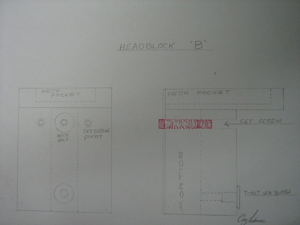
Dennis , we are trying for an external adjusting system, that is ,if we can design one that will work reliably. It would be a whole lot easier to deal with an internal adjustment with a locking screw . That's been handled by people like Dave without problems ,as far as I know. To be able to adjust the string action , without having to loosen the strings and dive into the soundhole would be a great advantage . This is what we are striving for, and hopefully achieve.

You mention the intonation thing again . We have covered that in a fair amount of detail , and discovered that this isn't an issue at all. This was confirmed by Dave who is experienced with his adjustable system , and also with my calculations showing that with a pivot point of 30 mm. from the fretboard , the string length only increases it's length by .093 mm. ( around 3 1/2 thou ) , when lowering the string action .5 mm above the twelfth fret. Intonation is of no concern.

Whatdoyareckon ?

Cheers Craig
I modeled what I was going to do in CAD, and saw about 4 thousandths (inches) difference in string length from the highest to the lowest reasonable adjustment. I believed I would not be able to detect a change in intonation when I changed the neck pitch, but it was easily heard. Maybe I was physically off further that the theoretical 4 thousandths. I have no argument with Dave's ears, but my physical guitar did have an intonation change with an action change. In fact, that is the major reason that I will change what I did last time. Not trying to beat a dead horse, just offering my observations, and for me it was an issue that I feel needs to be addressed in any future design I use. I'll get my pivot points as close to the strings as possible, and hope to be pleasantly surprised that Dave is correct and that the intonation becomes a non-issue. (But, I would feel foolish building without adjustable pivot points - just in case.)

The more I think this over, the more I think that setscrews can easily solve all of the engineering criteria, whether interior or exterior adjustment is desired.

I'm thinking the simpler the better, and the least possible chance of creating any possibility of buzzing the better. That's one reason I don't like the concept of additional screws (cap screws or setscrews) going through metal (t-nuts or threaded sleeves) if they don't absolutely have to.

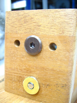
Think of a normal tripod. Three legs on the ground - perfect stability and adjustability. That's the model for using three setscrews from the interior of the guitar, which make contact with three metal discs epoxied into the neck heel. Three setscrews means complete flexibility in pitch and yaw of the neck. Hold the neck on to the guitar body with the pair of crossdowels and bolts. (Fleishman)

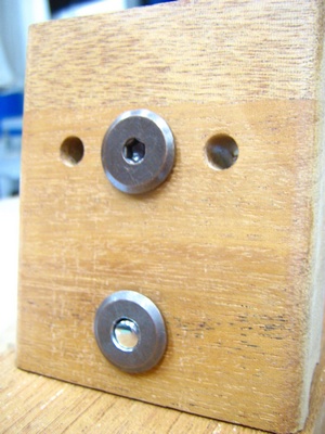
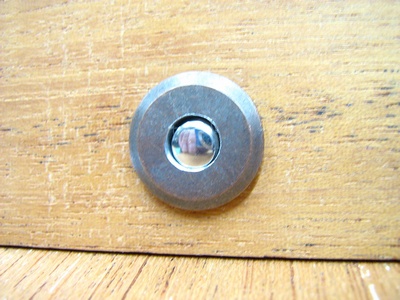
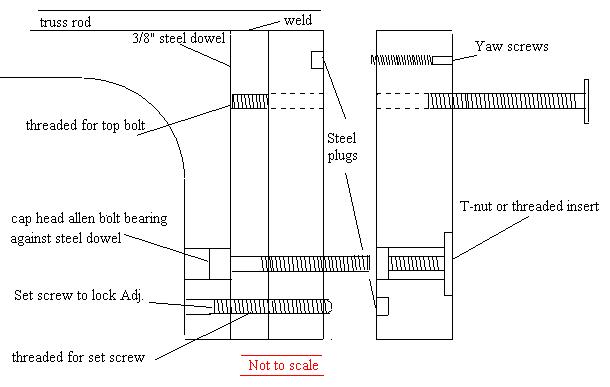
Now think of an altered tripod: two normal, adjustable legs, and one sawed-off fixed leg. At the end of the fixed leg, solder on a flat metal disc. For the tripod to regain perfect stability and adjustability, stick a single adjustable tripod leg into the ground, with the point facing up. Place the tripod so that the fixed disc contacts the upward pointing tripod leg stuck in the ground - then you have regained the adjustability. This is my mental model for the adjustable guitar neck joint where adjustment is done from the exterior. So, the neck has two metal discs epoxied in place (contact points for the two upper setscrews that are pointing outward from the neck block), and the neck block has a single metal disc epoxied in place (contact point for the single setscrew near the tip of the neck's stiletto, rounded, or flat heel.) With the three contact points, you have complete control over the adjustment of the pitch and yaw of the neck.

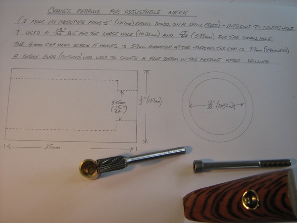
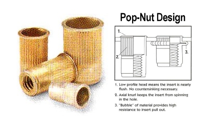
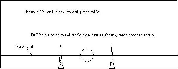
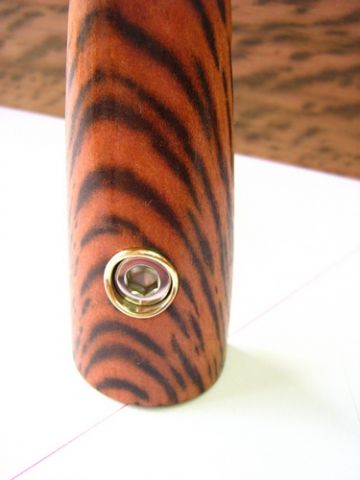
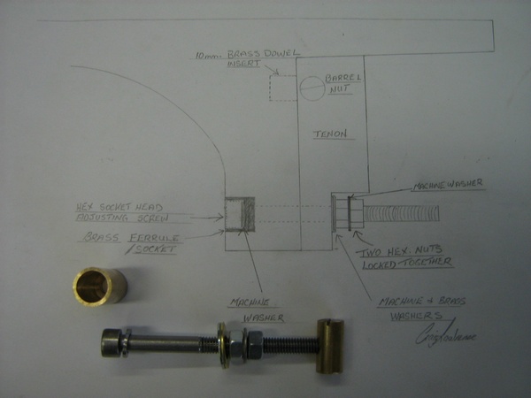
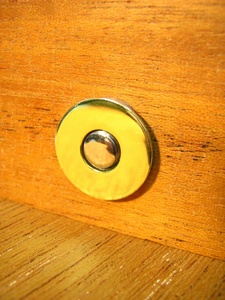
Using a setscrew in the heel (rather than a captured screw system) means no ferule is needed. (A metal or wood cap with a central hole could be used, for aesthetics, if desired. Or, a strap button with a hole could be used over the setscrew hole.) Before the wood heel cap is glued on, the neck heel would be drilled and a wood dowel inserted and glued-in. That would both strengthen the heel (especially a narrow stiletto heel) and provide cross grain rather than end grain wood for the setscrew threads to bite into. To further strengthen the heel, the tenon could remain nearly the full height of the heel, and the setscrew could pass through the tenon as well (with additional wood dowels inserted and glued into the tenon to provide additional cross grain.)

The setscrews, in wood, could not buzz. The neck is secured by a pair of (tried and tested true) crossdowels and bolts. The neck is easily removed by removing the two bolts.

I can see that it may be possible to make a minor adjustment in neck pitch (using only the solo bottom setscrew) without touching the big bolts. However, if the bolts are torqued *just right* to begin with, then tightening or loosening the solo setscrew has to change the torque on the bolts (especially the lower one) to *very slightly too tight* or *very slightly too loose*. To keep the system simple, this might be within the tolerance of compression and expansion of the components, but I would feel a bit more comfortable if a spring washer is placed under the bolt heads, allowing the engineered compression and expansion of that washer to handle those forces.

I'm still scribble-sketching how to get the upper pivot points (the upper setscrews and their corresponding metal discs) up as close to the fingerboard as possible, but yet be not too close to the edge of the neck block. Another consideration is keeping a good mass of wood under the fingerboard as a fingerboard extension platform, and how to contend with that. At the moment, I'm thinking about angling the upper setscrew holes, and then possibly angling the crossdowel bolt holes to counteract that angle (to prevent the neck from wanting to rise off the body further than intended.)

I'm certainly not recommending that anyone abandon their prototyping efforts, but thought I'd just express where my thinking has gone with this.

Dennis

p.s. Grant Goltz has just completed a second mini-tutorial on the Luthierforum, showing how he does his adjustable necks. If you want to check it out, here is a link: Grant Goltz Adjustable Neck Joint
Another damn Yank!

User avatar
Craig
Admin
Posts: 1090
Joined: Wed Sep 26, 2007 10:08 am
Location: N.S.W. in the bush

Post by Craig » Wed Mar 19, 2008 9:52 am

Dennis,
I've just quickly skipped through your above post and will read it in detail shortly,.

Thanks so much for that effort mate . In the meantime ,I wonder if you could post a plan of your ideas , so that it becomes clear to all . I just photograph my drawings , as you can see, ( simpler for me !)

Dave , Likewise , I'll give your post some thought , sounds like some good solutions there , even if it means me becoming a 'tugger' :lol: :lol:

I have sent off the ferrule plans to Bob for Rick to fabricate. See below :

These ferrules can be made on a drill press ( with vise ) as I have done , but it is fairly time consuming and difficult to get the hole centered perfectly. It can be done however !!!. Rick's help here is greatly appreciated . A huge thanks to Rick !

Image

EDIT : I've just realised I haven't included the thickness of the bottom floor/base of the ferrule which is 4 mm.

Cheers , Craig

User avatar
Allen
Blackwood
Posts: 5252
Joined: Thu Oct 11, 2007 5:39 pm
Location: Cairns, Australia
Contact:

Post by Allen » Wed Mar 19, 2008 6:22 pm

You know Craig. You should be able to build those ferrules on a wood lathe with a chuck. And a few of us should have access to one of those. If you send me the specs I'll see if I can do your design justice as well.
Allen R. McFarlen
https://www.brguitars.com
Facebook
Cairns, Australia

User avatar
James Mc
Blackwood
Posts: 246
Joined: Sat Dec 08, 2007 7:37 pm
Location: Townsville

Post by James Mc » Wed Mar 19, 2008 7:59 pm

I’m a fan of getting what I can off the rack…. There are many different threaded brass inserts available that I’m sure we could find something. The one that springs to mind is pop-nuts, popular with Panel Beaters and engineers everywhere; these little gems as cheap as chips and come in a range of sizes and metals. The idea is to drill a hole in the metal put in a pop-nut then pull it up as you would a pop-rivet. But you don’t need to pull them up and if you don’t you have a nice brass tube with a thread at the bottom.

Image

User avatar
Tom Morici
Blackwood
Posts: 103
Joined: Thu Nov 01, 2007 5:46 pm
Location: Montana, USA
Contact:

Post by Tom Morici » Wed Mar 19, 2008 8:04 pm

Allen,

A trick to center round stock for drilling. Chuck the round stock in the drill
press lower it down into the drill vise. tighten vise and secure vise to drill
table. Release the round stock from the drill chuck, insert drill bit, drill hole.
No vise or way to clamp down vise, do this.
Take a piece of 1x lumber the same width of your drill press table, this makes it easy to clamp down.
here's a pic of the details.
Image

I hope this helps!

Tom

User avatar
Craig
Admin
Posts: 1090
Joined: Wed Sep 26, 2007 10:08 am
Location: N.S.W. in the bush

Post by Craig » Wed Mar 19, 2008 10:55 pm

They are all great tips , thanks guys. I'm sure there are many of us that can make them, but there are probably others who are unable, due to tooling etc. I'm very grateful that Bob is able to have Rick make some up for those who want them.

The dimensions I have on the Ferrule plan are "just right" for the 6 mm. stainless screws we have in mind . They need be these measurements for them to do their job properly . I gave these above dimensions careful thought. Their job is very important as a bearing area for the screw . The walls of the ferrule (when epoxied in ) also share the load. The fact that they look pretty is a bonus , but not what they're all about.

I have them on the plan as over length at 25 mm. so that they can be filed back to suit the heel profile with length to spare. It's surprising how much length is required if you were to use a fairly pointy heel profile .


TOP PIVOTS ;

I played around with some more threads into a dummy mahogany headblock this evening ( with correct grain orientation).As top pivot screws.

The more I trial these things , the more I like them. I tryed a set screw ( also known as a grub screw here in Australia ) of 8 mm. diameter , and 40mm. ( 1 1/2 " ) long. They are as solid as a rock when they are in the Mahogany.I can't imagine them undoing. Far from it actually. The amount of resistance whilst turning them is very impressive. The fact that others have been using these successfully has me thinking they are the way to go . No worries about having to lock them me thinks !. , but probably important to trial differing size holes , to find which one suits . I have found 1 mm. smaller than the actual thread size to work out best. I have also trialed some 6 mm. long threaded cap screws ( same as the bottom adjuster screw ) , and they appear to work just as well .


I am trying to work towards resolving the top pivot design ,as it appears that's one part of the design we can agree on fairly quickly. I propose we adopt 8 mm. X 40 mm. set screws as our model .I'm going to try and get these in Stainless steel. Any builders wishing to use a deviation of these is free to do so of course .

If we can agree on this , it will leave us free to concentrate all our efforts soley on the bottom adjustment area . I feel it will keep our discussion/ thinktank more in order .

If we can resolve the bottom area , then we will probably look at something like the neck pocket excavation ,or whatever . Your views please gentlemen ?


Cheers , Craig

User avatar
Dave White
Blackwood
Posts: 452
Joined: Mon Nov 12, 2007 3:10 am
Location: Hughenden Valley, England
Contact:

Post by Dave White » Thu Mar 20, 2008 6:27 pm

Dennis,

Grant's is a simple and elegant system. It relies on the wood of the neck insert pocket bearing on the neck heel cheeks at the top to act as a pivot point and the strength in the spring to hold the system solid at the bottom of the heel in steady state and then push in and pull out as the bottom bolt is tightened or loosened. You could adapt it for external adjustment by putting an insert in the bottom of the neck block and reversing the bottom bolt. You'd be back to tristing the insert though.
Dave White
[url=http://www.defaoiteguitars.com]De Faoite Stringed Instruments[/url]

User avatar
Tom Morici
Blackwood
Posts: 103
Joined: Thu Nov 01, 2007 5:46 pm
Location: Montana, USA
Contact:

Post by Tom Morici » Thu Mar 20, 2008 7:56 pm

Dennis,

I do have to agree with Dave's comment on Grant's design, simple yet effective. I take forever to settle on any design, and my only concern
would be the spring itself, fatigue for one, and also possible "whammy"
effect. I do feel I am splitting hairs with this concern, and just take it as me playing Devil's advocate. All in all I do think it is a great design.

Dave,
I prefer your adjustable neck setup over Doolin's I don't care for the way the neck attachment bolts are trapped in his design, the ability to replace
a worn part is a big plus in my book.

Craig,
Thanks for explaining why you are having the Brass ferrules made 25mm
long I was going to ask about that, that's thinking ahead.

Tom

Rick Turner
Blackwood
Posts: 311
Joined: Sun Jan 13, 2008 10:22 am
Location: Santa Cruz, Ca.
Contact:

Post by Rick Turner » Mon Mar 24, 2008 6:57 am

I've been doing my adjustable tilt neck system since 2001, and it is indeed bases on the Howe Orme necks from the 1890s. To that I added the ability to move the entire neck in and out for global intonation adjustment. I later found a Larson Brothers patent that is nearly identical to what I'm doing.

I have not had a single potential client object to the visible hardware once they saw how easy it is to adjust the neck angle. Fifteen seconds is what it takes, and I tell them, "On your Martin (etc.) that would have cost about $400.00. It's only luthiers who get weird about the hardware stuff...too much of a focus on traditional aesthetics and not enough on functionality. Besides which, a bit of exposed hardware never stopped a banjo player from buying a MasterTone...

I'm making a run of necks this month and next; I'll photo the process with all the hardware.

One thing...I put a 3/8" steel dowel into the heel and it's welded as part of the truss rod. This takes most of the stress off the short grain of the heel and give me hardware in there that I tap threads into for a locking screw and a bearing surface for the action adjustment screw.

Also, I've refined this all a bit since the 2001 Ms. Antarctica guitar, so there's less of a gap between the heel face and the guitar body.

The thing is...this is really, really easy to do, once you have the hardware covered. And then you have complete parametric control over the neck angle, the "yaw" that affects how the strings are centered on the fingerboard, and the overall intonation. Plus you can set your saddle height and never have to mess with it which means you can find the ideal height for the strings above the top for tonal purposes.

Then there's the whole issue of getting the fingerboard off the top and getting more tonal response from the upper bout.

There will be a full photo essay on how we build these guitars coming up in the June/summer issue of Fretboard Journal...
Rick Turner
Guitar Maker, Experimenter, Diviner
www.renaissanceguitars.com
www.d-tar.com

User avatar
Tom Morici
Blackwood
Posts: 103
Joined: Thu Nov 01, 2007 5:46 pm
Location: Montana, USA
Contact:

Post by Tom Morici » Mon Mar 24, 2008 8:20 am

Rick,
Thanks for jumping in on this thread.

I assume the reason for welding your 3/8" steel dowel to the truss rod,
would be so you could pre-drill and tap the 3/8" steel dowel before it is installed into the heel, is this correct?

My other interest would be, the lower adjusting bolt threaded insert.
do you do anything that allows it to move up and down as the heel angle
changes. I find the lower bolt binds quickly as the heel is brought in.

I do know as long as the lower bolt is not too long, it will work fine.

Just curious of your thoughts on this.

Tom

Rick Turner
Blackwood
Posts: 311
Joined: Sun Jan 13, 2008 10:22 am
Location: Santa Cruz, Ca.
Contact:

Post by Rick Turner » Mon Mar 24, 2008 8:47 am

I use a threaded brass insert/tee nut on the inside of the body neck block, and I never have any binding problem. The amount of movement needed to achieve a good range of action is just not significant.

I've got small bolts up under the fingerboard on each side of the heel that go into threaded inserts in the heel face. These are the pivots on which the neck moves, and they are adjustable to control intonation and neck yaw. Then there's a long Allen head bolt that bears on the steel dowel in the heel and goes into the Tee nut in the neck block. Right below that is a lock screw threaded through the steel dowel that locks the whole neck into place when you are done adjusting it. To do an adustment, you back off the lock screw, and then turn the long bolt one way or the other, then re-tighten the lock screw.

It's just ridiculously easy...and maybe that's why some folks object! Got to make it more complicated...more difficult...hide it...spend more time on it...
Rick Turner
Guitar Maker, Experimenter, Diviner
www.renaissanceguitars.com
www.d-tar.com

User avatar
Craig
Admin
Posts: 1090
Joined: Wed Sep 26, 2007 10:08 am
Location: N.S.W. in the bush

Post by Craig » Mon Mar 24, 2008 10:36 am

Tom Morici wrote:Dennis,

I do have to agree with Dave's comment on Grant's design, simple yet effective. I take forever to settle on any design, and my only concern
would be the spring itself, fatigue for one, and also possible "whammy"
effect.

Tom
I have this same concern Tom.

Maybe we are a fussy lot down here Rick ,but the aesthetic issue is one we all consider to be fairly important.

I have been really thinking this thing through over the last few days and have finally arrived at this ,my latest design, which still includes my captured screw system , and ferrule etc.

I'm using a T-nut at the rear of the headblock rather than at the front as in Dave's 'missionary position'. The string pull is focused to the rear of the headblock rather than being held by an insert epoxied in place in the front. Just didn't like that part much . The only part I didn't like with the rear attachment was the look of a T-nut through the soundhole . It looks shithouse (sorry Rick , but I think it does matter ).

The T-nuts I am using have 1 degree of play in the thread , which I calculate to be 5 times more than required.

My method of installing this lower T-nut ,is to place the drill bit through the heel captured screw hole ( screw removed of course ) and drilling a hole through the headblock. This to be done after the neck has a trial "fit ". This would line up the headblock hole to the heel's captured screw system. The T-Nut could then be installed easily at the rear.

My new design also allows the headblock depth to be reduced back to 2 "

Folks, I present the :

'Craig Lawrence Adjustable Neck System' :lol: ( drum roll please ! :lol: )


Image


You'll note how the end of the stainless steel captured screw buffs up very well :


Image


Image


Image


An alternative , and one I'll talk about later is Stainless caphead screws:

Image


Yet , another pivot alternative ;(please ignore bottom barrel -older plan)


Image


My captured screw system ( but I've swapped out the barrel for a T-Nut) :


Image


An alternate lower T-Nut cap;

Image


Image


Cheers , everyone, Craig Lawrence
Last edited by Craig on Mon Mar 24, 2008 12:16 pm, edited 1 time in total.

Rick Turner
Blackwood
Posts: 311
Joined: Sun Jan 13, 2008 10:22 am
Location: Santa Cruz, Ca.
Contact:

Post by Rick Turner » Mon Mar 24, 2008 11:07 am

I am NOT using hardware store variety tee-nuts...it's a brass shouldered threaded insert. I just call it a tee-nut because that's how it basically works. The only aesthetic concerns become the exposed pivot bolts, the gap between heel face and the end of the guitar, and the two holes in the heel for access to the lock screw and the adjustment bolt. Given my long love of the Howe Orme design as well as other vintage instruments (think Larsons & banjos) that have exposed hardware, I don't have a problem with all this, and neither, apparently, do my customers, I'm happy to say. I think we can be too hung up on particular visual details based on one particular tradition, adn to me that is not what a great guitar is about. I don't care that these don't look like Martins...

There are several well considered reasons I'm not mortising the heel into end of the guitar, too. 1) I make too many variations on neck width/heel width to want to bother tooling for that, but more important: 2) I like having a minimal sized neck block (1/2" Baltic birch ply, like the tailblock). 3) I want all the hardware to be easily accessed and adjustable without taking off the strings or the neck. 4) I want my neck heels to be flush with the sides in a cutaway design.

This all leads to exposed and easily adjusted hardware. I'm not building these for a mass market, and frankly, if someone doesn't like the way I build guitars, they can buy one elsewhere!
Rick Turner
Guitar Maker, Experimenter, Diviner
www.renaissanceguitars.com
www.d-tar.com

User avatar
Craig
Admin
Posts: 1090
Joined: Wed Sep 26, 2007 10:08 am
Location: N.S.W. in the bush

Post by Craig » Mon Mar 24, 2008 12:58 pm

A couple of points I should have made clear about my design , especially after reading Rick's post ;

The neck angle is easily adjustable via ONE stainless steel external adjuster, with no need to take off the strings or neck etc.

All the hardware in my design is easily accessed and replaceable if that should ever become necessary.

I prefer a mortice and tenon arrangement. I see the headblock as the heart of the instrument ,with the back, soundboard, sides, and neck all attached to it.

My design has NO aesthetic issues others may be concerned about.

No problems with flush sides cutaway , and in fact ,it's what I'll be doing.

A T-nut could easily be fabricated ( like Rick's ) , instead of using a store bought T-Nut and cap ( as in my above post).

Rick , I have no doubt the Howe Orme system works well . To me , it's the look of the system and it's many aesthetic issues, that not all would embrace. Others ,may of course differ from this view.

Hoping I'm not sounding too defensive here :lol: :lol:


Cheers , Craig

User avatar
Allen
Blackwood
Posts: 5252
Joined: Thu Oct 11, 2007 5:39 pm
Location: Cairns, Australia
Contact:

Post by Allen » Mon Mar 24, 2008 1:32 pm

How much depth are you allowing for the fingerboard support in the neck block Craig. Is it still at 20 mm?
Allen R. McFarlen
https://www.brguitars.com
Facebook
Cairns, Australia

Rick Turner
Blackwood
Posts: 311
Joined: Sun Jan 13, 2008 10:22 am
Location: Santa Cruz, Ca.
Contact:

Post by Rick Turner » Mon Mar 24, 2008 1:35 pm

I've cut the headblock down to absolute minimum and have dealt with the forces on it by using flying buttress braces...a double "A-line" of carbon fiber rods that take the pressure on the headblock and transfer it down into the sides at the waist. I've repaired too many guitars and mandolins that were collapsing with top cracks on either side of the fingerboard to trust in some sort of massive headblock. I just don't agree that the headblock has to be the structural heart of the instrument, though it is certainly a focus of forces. You'd be amazed at how blase players are about the aesthetics. They recognize a good thing when they see it, and most just don't give a rats arse about a little bit of hardware and a small gap. In fact, they all immediately understand the implications of the tilting neck as a player-friendly feature.

Over the years I've seen many luthiers do things just because they were difficult. I like easy. This neck attachment is the fastest way I can think of to securely attach a neck to a guitar body. All the fitting is mechanical, and it's almost infinitely adaptable to different neck widths, feel, and scale length.

In fact, I'm currently making a second neck for a guitar I made last year so my client can switch back and forth between a standard 25.5" scale length and a baritone at 27". I figure it will take him about five minutes to swap necks in his recording studio...
Rick Turner
Guitar Maker, Experimenter, Diviner
www.renaissanceguitars.com
www.d-tar.com

User avatar
Craig
Admin
Posts: 1090
Joined: Wed Sep 26, 2007 10:08 am
Location: N.S.W. in the bush

Post by Craig » Mon Mar 24, 2008 2:46 pm

I'm not wanting to get into a pissing match here Rick..

This thread has been going on for quite a while . During that time , we have considered what we want, by way of an adjustable neck system. I think I have come up with a good system that meets peoples needs. It's an incredibly simple system and doesn't require an engineering degree to fabricate , which was one of my intentions from the outset.

A system that's easier than all others I have studied. A system that the average luthier can make with ease. A system that looks aesthetically pleasing.

You have come in, nearing the tail end of our discussion ,puting forth the Howe Orme system as the only system we should look at.

Could you please post a picture of your system so that others can see it visually for what it really is !

Regards the neck block causing a crack in the soundboard. That's just scare tactics and a load of rubbish. Good Soundboard bracing takes care of any issues that may want to arise.
Last edited by Craig on Mon Mar 24, 2008 6:23 pm, edited 2 times in total.

User avatar
Craig
Admin
Posts: 1090
Joined: Wed Sep 26, 2007 10:08 am
Location: N.S.W. in the bush

Post by Craig » Mon Mar 24, 2008 3:09 pm

Sorry Allen , I missed your post.
At this stage I still have 20mm. but that may be subject to change as we work our way to that area.

Cheers, Craig

User avatar
Tom Morici
Blackwood
Posts: 103
Joined: Thu Nov 01, 2007 5:46 pm
Location: Montana, USA
Contact:

Post by Tom Morici » Mon Mar 24, 2008 4:23 pm

Rick,
I tend to agree with you, luthiers worry more about things (Im guilty) than
our customers would even think or concern themselves with.

And as far as I know, the perfect guitar that everyone loves, has not been built yet.

We all have our own views that we feel is the best, but lets face it, your
tooling and others are not the same. Most designs are based on what we find easy.

After reading your description of your Adj. system I come up with this.
Patterned after the Larson Bro's design. With your improvements.

I am still curious as to why you weld the steel dowel to the trust rod.
Im sure you have a clever reason for this.
Image

Craig,

I like the cap for the t-nut, but I am a long way from settling on a design.
I would prefer that we keep brainstorming. The more designs we see the better as far as I am concerned. In the end we may follow a design shown
but more than likely it with be an adaptation of all the designs.

James,
I would still like to see the scissor Adj you talked about.

Tom

User avatar
Craig
Admin
Posts: 1090
Joined: Wed Sep 26, 2007 10:08 am
Location: N.S.W. in the bush

Post by Craig » Mon Mar 24, 2008 6:41 pm

Tom,
I'm with you 100 % that we should leave all options open. Not only that , but I'm sure that there are those who prefer to use a different system alltogether, and that's fine. It's a personal choice.

I would also like to make completley clear that the design I arrived at above, is in a large part, due to the input from you guys , and not mine alone. There were a few things I overlooked along the way and guys like Dave , Tom, Dennis , Allen ,James , Paul, Kim, Dom, Bob( sorry for the people I've missed ),and others helped with this by way of finding a flaw , or suggesting a better alternative.

If my design can be approved upon , that's fantastic Too !. It's just what I've finally come up with after my careful consideration. Not forgetting that this ain't the whole picture yet ! . There are still a few other things to tend to , by way of pockets etc.

Regarding your plan Tom , That 3/8 " steel rod looks awefully heavy , and you will still need 2 ferrules, whereas my one ferrule does the lot.

Cheers , Craig

User avatar
Tom Morici
Blackwood
Posts: 103
Joined: Thu Nov 01, 2007 5:46 pm
Location: Montana, USA
Contact:

Post by Tom Morici » Mon Mar 24, 2008 7:14 pm

Craig,
Well said,where just swapping ideas.

The picture depicts what I felt Rick had described as the way his Adj.
system would look. Since Rick uses 3/4" baltic birch for a neck block.
It may be a trade off as for what total weight may be.

I do like your ferrule, more to protect the hole, and it does give it more of a finished look,the added strenght is a plus.

Tom

User avatar
Allen
Blackwood
Posts: 5252
Joined: Thu Oct 11, 2007 5:39 pm
Location: Cairns, Australia
Contact:

Post by Allen » Mon Mar 24, 2008 7:36 pm

The neck block is looking really 'finished' now Craig.

Let me get this straight in my head. As it stands now, the adjusting screw is going into the t-nut without a set screw to lock down once the neck is adjusted. The t-nut is pulling into the neck block from string tension, this is good. And do you feel it's anchored firmly enough into the neck block to stop it from being pushed back out from the user pulling back on the neck. I think that this is unlikely, especially under string tension, and the amount of free play that you would have in the adjustment isn't going to be that great, but I suppose it's a possible consideration.
Allen R. McFarlen
https://www.brguitars.com
Facebook
Cairns, Australia

User avatar
Craig
Admin
Posts: 1090
Joined: Wed Sep 26, 2007 10:08 am
Location: N.S.W. in the bush

Post by Craig » Mon Mar 24, 2008 9:16 pm

Allen, Yes I gave that matter of the T-Nut being dislodged backwards some thought. Considering the string pull is trying to pull the thing in , and that it's epoxied in , I'm thinking it unlikely. All the major stress is directed the other way, but still definatley worth considering. I guess if it had a huge crunch, something might happen. It would be a very easy repair to reglue it in, if it ever did.

I calculated the play in the T-Nut to be 1 degree free travel. This about 5 times more than required. A good idea to centre the T-Nut properly when installing it with epoxy , would be to use the adjuster screw itself ( locking hex nuts removed )to clamp it in position. This would centre the T-Nuts thread to the adjuster screw.

Tom,
I just had another thought regarding that 3/8 " rod.
A builder friend of mine and myself thought that a 3/8 " rod vertically up the heel would be a better idea than Cumpiano's barrels system , so we set to and tryed drilling two parallel holes a set distance apart , both being centred in the very middle of the rod, and then tap the thread in them. Anyone that makes their own barrels will know what I mean. The drill bit has a mind of it's own and wants to go anywhere but dead center. I tryed centre punches , filing a flat spot for the drill to start. It happened ,but after a fair while :lol: . I now have a centering bit , so I may have better luck. Anyhow we decided that square section instead of the round bar would make our idea more possible. We then realised it was going to make the whole thing too heavy . The 3/8 " round weighed in at around 40 grams as it was !.

Needless to say we went back to the barrel idea :lol:

Rick obviously doesn't have this problem of drilling three holes in his rods, as he would have the tooling and skill required.


Cheers , Craig

Rick Turner
Blackwood
Posts: 311
Joined: Sun Jan 13, 2008 10:22 am
Location: Santa Cruz, Ca.
Contact:

Post by Rick Turner » Mon Mar 24, 2008 11:31 pm

Lose the top bolt, and put the yaw/intonation screws into the face of the heel with heads bearing against the outside of the guitar, and you've got it. Everything is adjustable from the outside of the guitar with full string tension on.

I use 1/2" Baltic birch for the head/neck block and it's supported by four flying buttresses to the waist.

Yes, the 3/8 steel adds a bit of weight, but it's right there in the heel, and it does do the job. That's not a place in a guitar where weight matters much.

I weld the steel dowel to the upper flat bar of the truss rod, and the turning portion of the rod itself threads through it so it becomes the end block of the Blanchard/Allied truss rod. I get the "electric" guitar rods and cut them down and then weld on the steel dowel. Well, actually I have one of our local bike makers do the weld, but we do the machine work here.

BTW, don't be afraid of working with steel. It's not that big a deal to drill and tap. I do a bit of milling as I've got a medium size vertical mill, but I could do all the basic work with a hacksaw, drill press, and hand files if need be.
Rick Turner
Guitar Maker, Experimenter, Diviner
www.renaissanceguitars.com
www.d-tar.com

Post Reply

Who is online

Users browsing this forum: No registered users and 71 guests