ANZLF Adjustable Neck Joint Group Discussion

Got a new way of doing something? Or maybe an old method that needs some clarification.

Moderators: kiwigeo, Jeremy D

Post Reply
User avatar
Craig
Admin
Posts: 1090
Joined: Wed Sep 26, 2007 10:08 am
Location: N.S.W. in the bush

Post by Craig » Sun Mar 09, 2008 9:50 am

Allen , The two locked hex nuts ( as per my plan) seem hard to beat and particularly when you consider the 170 odd pound of string pull as Dave mentioned. I'd also sooner stay away from having to rely on products such as locktite. The slip washer isn't going to like having it's neighbouring nut being soldered me thinks :?

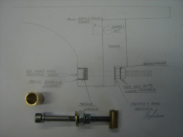
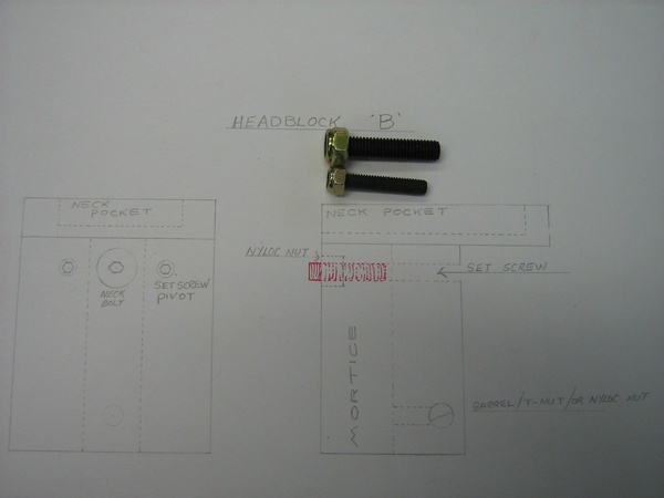
In every design there will always be a spot that is under more stress than other parts of the overall design. If it were to be the socket head allen head adjusting screw in this case , then lets address that : I have a washer and slip washer between the screw's head and surface of the heel. I would probably in actual fact like to see that screw head have a larger footprint than the 10mm it has , but that would demand a larger hole , if it were to be rebated into the heel. Could make it make it a bit unsightly. I think after initial bedding in ,the 10 mm.diameter of the head would become quite stable. A resolve or aid should there be a problem , might be to simply put a couple of drops of C.A. in the heels rebate area to harden up the wood before assembly.

That's funny Dom. :lol: I like the gentlemans walking stick in particular :lol: :lol:

Some guys go to the trouble of putting their label over their bolts on a bolt on set-up for that very reason. I've not bothered. As bolt-ons become more popular which seems the case , those folk will soon become educated to the" whys and hows."

Kim ,I take your point and understand that frequent adjustments to the neck angle may become a " hobby horse " to some folk, especially with this system being such an easy and quick adjuster. I don't see any harm in that. After all , if the system works well , is solid and the system itself is easily serviced ( by way of removing any slack that may arise ) , it's doing what it was designed to do.

Good morning folks ! :lol:

Cheers, Craig

User avatar
Craig
Admin
Posts: 1090
Joined: Wed Sep 26, 2007 10:08 am
Location: N.S.W. in the bush

Post by Craig » Sun Mar 09, 2008 5:34 pm

O.K. I have my calculations done :

Based on a 25.4 " ( 645 mm.) scale with a pivot point 30 mm. away from the fretboard.


To lower the strings above the twelfth fret .5 mm ( Which I consider a fair whack ! ) it will cause a string length increase of .0931677 mm. or .003668 " for the imperial minded . In other words the twelfth fret moves around 3 1/2 thou away from the saddle, or not quite one tenth of a mm.

I used a twelve fret body join for ease in calculation. A fourteen fretter would be only marginally different..

As you can see , it's such a slight change , it 's not worth any concern.

I forsee a more common adjustment as lowering the strings .25 mm..

In that case ,the twelfth fret moves away from the saddle ( in other words, the string length increases ) by.0465838 mm. ( not quite a twentyth of a mm.) or .001834 " ( say 2 thou.),,,,,,,,,, no concern whatsoever.

I would appreciate Dave , our mathematician, verify these figures , or anyone else for that matter, but I'm pretty sure they're right. I was surprised how little the length increase is ,and don't wonder why Doolin locked his pivot adjusters up after final set up of the guitar.

Makes you also think that the Taylor front shims are there mainly as an aid in assembly 'set-up'.

Another issue solved ! :lol:

Cheers , Craig

User avatar
Tom Morici
Blackwood
Posts: 103
Joined: Thu Nov 01, 2007 5:46 pm
Location: Montana, USA
Contact:

Post by Tom Morici » Sun Mar 09, 2008 6:57 pm

Craig,
You do understand my concept correctly. And I did think of using two
screws left and right of the wooden plug, good catch there. I also had felt
one screw pushing on one edge of a tight fitting plug would also have a binding affect. And to show two screws I would have to draw an end view
to show what I was talking about, ok so I got lazy.
I do own a lathe so my first idea would have been a little more complex.
I tried to make it simple, but your idea is simpler.

Now with that said. I see your simple and raise you a simple :lol:
Why do we need any more than a hex head bolt with a slip washer.
The pressure is always on the head of the hex bolt, the top swells and rises so we turn the bolt in to tilt the neck back. When the top shrinks and settles down we turn the bolt out and the neck tilts forward.

We would have to re-tune either way. The pull of the strings and the pivot of the heel assures that there is always pressure on the bolt head.
Ok am I missing something?

Tom

User avatar
Allen
Blackwood
Posts: 5252
Joined: Thu Oct 11, 2007 5:39 pm
Location: Cairns, Australia
Contact:

Post by Allen » Sun Mar 09, 2008 7:22 pm

the only way were going to be sure that it works is to actually build it.
Allen R. McFarlen
https://www.brguitars.com
Facebook
Cairns, Australia

User avatar
Craig
Admin
Posts: 1090
Joined: Wed Sep 26, 2007 10:08 am
Location: N.S.W. in the bush

Post by Craig » Sun Mar 09, 2008 8:28 pm

Allen I think I just edited your post out by mistake :oops: I went to quote your line " the only way to be sure it's going to work is to actually build it " but must have pushed the edit button instead of the Quote button . Sorry mate :oops: :oops: Would you mind posting that again :oops: :oops:

User avatar
Kim
Admin
Posts: 4376
Joined: Wed Sep 26, 2007 8:32 pm
Location: South of Perth WA

Post by Kim » Sun Mar 09, 2008 8:36 pm

Ahh Haaa, the old "sorry I deleted your post mate!" trick hey Craig???? Obviously a KGB graduate there buddie. :lol: :lol: :lol:

Still think the adjustment tool should be one that can only be held with the eye socket, this would demand an element of dedication to the task :D

Cheers

Kim

User avatar
Craig
Admin
Posts: 1090
Joined: Wed Sep 26, 2007 10:08 am
Location: N.S.W. in the bush

Post by Craig » Sun Mar 09, 2008 9:00 pm

Try again ::


Very true Allen ! and I think we are getting closer to that stage.

Yes Tom I think you have it in a nutshell . Just to clarrify though . Turning the screw clockwise will bring the strings closer to the neck and visa versa.

I like your larger bearing surface though Tom ( a nut being wider than my planned socket head screw ( 10 mm. diameter head) , . Trouble is , a screw with a wider head would look unsightly IMO , and may not be necessary considering it has a washer and slip washer beneath it. I think I'll be letting a couple of drops of C.A. penetrate and harden in the screw's rebate all the same. If a brass type surround was to be used to line the screw's rebate, a washer larger than 10 mm. could be used and put in place before installing the brass rebate liner . Actually , if it had a rolled collar at it's surface , that bearing surface would increase further still . HMMMMMM,,,, I thinks me like that idea.


Man, your a funny guy Kim :lol: :lol:


Cheers , Craig Lawrence,,,, K.G.B :lol: :lol:

User avatar
matthew
Blackwood
Posts: 1192
Joined: Mon Oct 08, 2007 1:16 pm
Location: Sydney, Inner West
Contact:

Post by matthew » Sun Mar 09, 2008 10:57 pm

Wouldn't a height-adjustable bridge achieve the same results? Is this impossible on an acoustic guitar?

User avatar
Dave White
Blackwood
Posts: 452
Joined: Mon Nov 12, 2007 3:10 am
Location: Hughenden Valley, England
Contact:

Post by Dave White » Mon Mar 10, 2008 12:07 am

matthew wrote:Wouldn't a height-adjustable bridge achieve the same results? Is this impossible on an acoustic guitar?
Matthew,

Part of the assumption around an adjustable neck is that you can "optimise" the guitars tone around a certain heght you want the top of the saddle to be above the soundboard and hence the way the strings drive the top. Then you can have differetnt action settings for playability and the same saddle height. As a builder you may or may not hold this view of course - I mean that generically rather than you personally.

Some US makers make a summer and winter saddle of different heights that can be swapped out in the different humidity conditions. This is adjusting the string height at the saddle. If you made and adjustable bridge height it would do a similar job but you would have to make sure that the acoustic coupling with the top remaiined in tact as the height adjusted - again assuming as a builder that you think it impacts on tone.

If the neck angle geometry is "wrong" in terms of impacting playability then a neck angle change rather than string height change at the saddle is the solution you need.
Dave White
[url=http://www.defaoiteguitars.com]De Faoite Stringed Instruments[/url]

User avatar
Dave White
Blackwood
Posts: 452
Joined: Mon Nov 12, 2007 3:10 am
Location: Hughenden Valley, England
Contact:

Post by Dave White » Mon Mar 10, 2008 12:10 am

Tom Morici wrote: We would have to re-tune either way. The pull of the strings and the pivot of the heel assures that there is always pressure on the bolt head.
Ok am I missing something?
Tom,

The other thing to consider is neck stability under the players style. There are always those that use the neck as a whammy bar :D
Dave White
[url=http://www.defaoiteguitars.com]De Faoite Stringed Instruments[/url]

User avatar
Dave White
Blackwood
Posts: 452
Joined: Mon Nov 12, 2007 3:10 am
Location: Hughenden Valley, England
Contact:

Post by Dave White » Mon Mar 10, 2008 12:12 am

Dominic wrote:The reason I was thinking about hidden hardware was because a friend said he saw a taylor that had the bolts in the fingerboard and he was disgusted. He thought it was a sign of cheap production. This can be overcome of course with marketing, electric guitars are covered in bolts and people love them, ... anyway,.
Then my brain started thinking, (Note from author: this could go anywhere)
Where could you put the long tool.
Dom,

You could also solve that problem by telling your friend to go and buy another guitar that met his requirements sonically and aesthetically - there are lots to choose from. In this case I could also think of another place to put the long tool :D - ooh is that another Aussie euphamism?

I'm very picky about who I let buy my instruments.
Dave White
[url=http://www.defaoiteguitars.com]De Faoite Stringed Instruments[/url]

User avatar
Dave White
Blackwood
Posts: 452
Joined: Mon Nov 12, 2007 3:10 am
Location: Hughenden Valley, England
Contact:

Post by Dave White » Mon Mar 10, 2008 12:22 am

Craig L wrote: I would appreciate Dave , our mathematician, verify these figures , or anyone else for that matter, but I'm pretty sure they're right. I was surprised how little the length increase is ,and don't wonder why Doolin locked his pivot adjusters up after final set up of the guitar.
Craig,

I'm getting old and so use those faculties only in dire emergencies :D What I do know from having made seven instruments with adjustable neck systems, and adjusted and played them with different actions is that intonation problems are not an issue as you adjust within "normal player" ranges. I also know that the top two set screws are (hopefully) adjusted rarely if at all - their job is to stay rock solid when you have set them and I can see why Mike Doolin glues them in. I like to plan for everything and am greedy so have aimed to make them rock solid and adjustable if necessary. If you are going to play around with altered tunings and different string gauges then there may be slight tweaks on the compensated scale lengths you might want to do. As I say - I see the top set screws as a rarely if ever to be adjusted thing.
Dave White
[url=http://www.defaoiteguitars.com]De Faoite Stringed Instruments[/url]

User avatar
Dominic
Blackwood
Posts: 1098
Joined: Thu Jan 10, 2008 8:58 am
Location: Canberra

Post by Dominic » Mon Mar 10, 2008 7:56 am

Dave,
In this case I could also think of another place to put the long tool - ooh is that another Aussie euphamism?
we save that last option for storing the long tool for when a customer (hypothetically speaking as i have none) comes back complaining that the guitar only plays a G cord, but is useless at Ds and As, and F, no way. Unfortunately once inserted removal is no longer the responsibility of the luthier. In fact he may even be prohibited from doing so under our local laws.
Knowing where this could end (using a long tool), I don't think it would take long for people (or may mate) to get used to seeing an adjusting screw in the heal.
So who is going to build this thing?
Dom

User avatar
Craig
Admin
Posts: 1090
Joined: Wed Sep 26, 2007 10:08 am
Location: N.S.W. in the bush

Post by Craig » Mon Mar 10, 2008 9:20 am

Dominic wrote: So who is going to build this thing?
Dom
I'll put my hand up here. I want to build a test mule type guitar anyway with an alternate soundboard and a few other things. It won't be pretty, might even be down right ugly if I try hard enough :lol: . I won't worry with the aesthetics and concern myself with function only. Even so , It'll take me a while .

I'm off to Tamworth tomorrow, and will call in at Bearfast to see what hardware is available off the shelf. I'll be seeking the long threaded adjusting screw . I have my doubts on that one being available, but I hope I'm wrong here. It may be one item in my plan that will have to be fabricated , but that's not a difficult thing to handle.

I'll also draw an updated plan and post it when I get a moment.

I can't believe how many gifted comedians there are on this forum :lol: Well , if any of you guys fail as a world beating luthier , at least you have an alternative :lol: :lol:

Cheers , Craig

User avatar
Tom Morici
Blackwood
Posts: 103
Joined: Thu Nov 01, 2007 5:46 pm
Location: Montana, USA
Contact:

Post by Tom Morici » Mon Mar 10, 2008 6:37 pm

Allen,

Your statement:
"the only way were going to be sure that it works is to actually build it."
This says it all, it is the proof of the pudding.


Craig, You wrote:

"Yes Tom I think you have it in a nutshell . Just to clarrify though . Turning the screw clockwise will bring the strings closer to the neck and visa versa."

Yes to be clear, when I said turn the screw in, that would be clockwise for me also. I use CA as a wood hardener for all metal to wood attachments
it mite be overkill but it makes me feel better.

Dave, you wrote:

"The other thing to consider is neck stability under the players style. There are always those that use the neck as a whammy bar"

Yes that did cross my mind, but I think due to the bending forces that will
occur on a long hex head bolt used as a pivot adjustment, would cause the bolt to bind and may be stiffer than one may think.
Even without the string tension there is a limit to how far you could pull
the heel in without binding the bolt. At least that is how I see it.

Hey and if I am wrong I'll try and find one of those "whammy bar players"
and sell it as a special feature. It will cost more of course! :lol:

Some may already know this, but for those that don't. The Larson brothers where building guitars with adj. necks in the 30's.

They had a number of styles that they used, this includes the two screws
against steel plugs at the top of the heel and adjustment screw(external)
at the lower end of the heel. Another had the adj screws in the fretboard.
Along with another Adj. screw in the heel.
Still another had a long rod going threw the heel to the tailblock, the adj.
was made with a strap button nut. This is just a few.

The older we get, the more we learn. "It's not new, just new too you"

Tom

User avatar
Allen
Blackwood
Posts: 5252
Joined: Thu Oct 11, 2007 5:39 pm
Location: Cairns, Australia
Contact:

Post by Allen » Mon Mar 10, 2008 7:28 pm

Thanks Tom for pointing out the the older we get, the less we know. :lol:

Ok Craig, we want to see some progress on this. No bludging now. Post some photos. 8)

My next build in going to be the size 5 terz, and it's going to be a traditional looking instrument, so I'm going to be using an adjustable neck, but adjust from the inside.
Allen R. McFarlen
https://www.brguitars.com
Facebook
Cairns, Australia

User avatar
Tom Morici
Blackwood
Posts: 103
Joined: Thu Nov 01, 2007 5:46 pm
Location: Montana, USA
Contact:

Post by Tom Morici » Tue Mar 11, 2008 4:01 am

Allen,

Good one, thats what I get for trying to say something clever.
:oops: :lol:

Tom

User avatar
Craig
Admin
Posts: 1090
Joined: Wed Sep 26, 2007 10:08 am
Location: N.S.W. in the bush

Post by Craig » Sat Mar 15, 2008 11:36 pm

I've made some good progress ,and here are my new plans.

Bearfast had the socket head screws with 1 inch long type threads as expected. They had them in black steel and Stainless steel . I thought the black ones would be easier to run a die down , but not so ! . Turns out the black ones have a hardness of K 12 . , while the stainless are around K 6 or 7. That's good ,because I wanted the stainless ones anyway.
As you can see I've successfully ran the die ( with cutting oil ) to their required thread lengths. No probs. !


Image


I have decided to leave out the nylon type slip washers and use brass washers instead.. Others may choose to use slip washers , I was afraid they would begin to compress and " squeeze out " , but I may be completley wrong here . This plan has the adjusting screw and washer bearing against the 4 mm thick base of the brass ferrule .

New to my design also is the brass ferrule for the adjusting screw. I see this piece as an important stuctural element . By using the 1/2 inch ferrule , it increases the bearing surface at the heel considerably. Not only by having a larger footprint , but because I'll epoxy it in , the walls of the ferrule/socket will share some of the load . The bearing surface area I was concerned about ( around the adjusting screw ) , I believe has now been rectified. It'll also look good which is another good thing :lol:

No such ferrules are available off the shelf ( as far as I know ), so I purchased some 1/2 " brass dowel to make my own .

The very best news is that , I can prepare all the hardware myself with out need for anyone to fabricate it for me . More on making the ferrule later : Questions ,comments, critique welcome.

More to come :

Cheers Craig Lawrence
Last edited by Craig on Sun Mar 16, 2008 12:48 am, edited 1 time in total.

User avatar
Craig
Admin
Posts: 1090
Joined: Wed Sep 26, 2007 10:08 am
Location: N.S.W. in the bush

Post by Craig » Sun Mar 16, 2008 12:08 am

My plan of the headblock shows 6 mm. socket screws as the pivot adjusters which go into T-nuts . The T-nuts shown are in their store bought state , I'll be cutting off the barbs on them and fashion the flanges to suit the heel profile shape before installing them into the headblock. They have a good long thread capacty and take up little space. The pivot screws are locked in position via the locking nut and washer against the face of the headblock.

I really like the look of these !! :D :D

Image


You'll note , I'm using a barrel bolt in the headblock. A threaded insert would probably have enough play in the thread to handle angle adjustments , but I'm not taking any chances , and besides , the barrel looks a lot more substantial than a nyloc nut I tryed. I don't think there is any need to have a locking type thread there as there is enough friction between the adjusting screw head and the 2 locking hex screws ,that I doubt it could undo itself.


Here's an alternative idea for those wanting to use set screws. I have pictured 6 mm. and 8 mm. screws . The 8 mm. look great but may be a bit of a squeeze fitting the 8mm. nyloc nut in the headblock without going to a straight heel ( as opposed to a stilletto type ) This system is a tad lighter , but relies on the durability of the Nyloc . Not that I would expect these pivots to be adjusted much, if at all. Their threads aren't all that long either ,when you discount the room the nylon takes up. At this stage , I think I prefer Headblock A .

Image


More to come :

Cheers , Craig Lawrence
Last edited by Craig on Sun Mar 16, 2008 12:43 am, edited 1 time in total.

User avatar
Craig
Admin
Posts: 1090
Joined: Wed Sep 26, 2007 10:08 am
Location: N.S.W. in the bush

Post by Craig » Sun Mar 16, 2008 12:33 am

As I mentioned above, This whole system can be fabricated by the average luthier which was one of my intents. The brass ferrule / socket is some thing that a lathe might handle with ease , but not having a lathe I ued a drill press and drill press vise. I drilled a 13 /32 " ( 10.32 mm) hole in the 1/2 " brass dowel after first drilling a 15/64 ( 5.95 mm. ) hole for the screw shaft . This was difficult to get centered ,,, but can be done with a good drill press and vise . After drilling the big hole , I chucked a rotary burr I purchased especially for the job ( pictured ). I set the depth stop on my drill press for a couple of mm. deeper than the existing hole , and it left a perfectly flat bottom in the ferrule for the screw and washer to bear against .

I have left around a 3 to 4 mm. floor at the base of the ferrule.
Should look pretty groovy when the brass is rounded over and polished . I'll also polish the head of the stainless screw.

The ferrule pictured is basically a blank . I've left it way over length so I can trim it to the heel's outside profile later on and round the edges etc.


Image


Incidently , my calculations show that a half turn of the adjustment screw should raise or lower the strings .5 mm. When I get a moment ,I'll work out how much that raises or lowers the string's pitch and tension.

Your comments guys ?


Cheers Craig Lawrence

User avatar
Dave White
Blackwood
Posts: 452
Joined: Mon Nov 12, 2007 3:10 am
Location: Hughenden Valley, England
Contact:

Post by Dave White » Sun Mar 16, 2008 1:20 am

Craig,

That's looking good and interesting so far. Very neat. Only one comment/question about the top pivots. On your first design, I'm not sure how the lock-nut functions - all of the pressure is pushing the bolt back into the soundhole so is this to stop vibrations loosening the bolt in the T-nut? If so maybe you need two lock nuts tightening against each other.

On your second design I'd be nervous about relying on the nyloc nut thread as the only failsafe against the backwards push from the neck/strings on the set screws. As I say, this part of the system needs to be rock solid in its "steady state".
Dave White
[url=http://www.defaoiteguitars.com]De Faoite Stringed Instruments[/url]

User avatar
Allen
Blackwood
Posts: 5252
Joined: Thu Oct 11, 2007 5:39 pm
Location: Cairns, Australia
Contact:

Post by Allen » Sun Mar 16, 2008 7:59 am

That's looking fantastic Craig. I'm most impressed. Those T-nuts for the top adjusting screws look like a big improvement as well. I presume that you will but some brass dowel in the neck for the T-nut bolt to bear against?

How much room have you left for the fret board extension?
Allen R. McFarlen
https://www.brguitars.com
Facebook
Cairns, Australia

User avatar
Craig
Admin
Posts: 1090
Joined: Wed Sep 26, 2007 10:08 am
Location: N.S.W. in the bush

Post by Craig » Sun Mar 16, 2008 8:37 am

Thanks Dave,
To explain headblock 'A' :

After final adjustment to the pivot screws , I then tighten the locknut and washer against the headblock face. This should lock the pivot screw tightly in position ( friction ). You may be correct in that two locking nuts may work better here , but my feeling is that a second one may not be required. The beauty of my designs are that all the hardware pieces ( except the ferrule and T-nuts) , can easily be undone /replaced , or added to, so adding a second nut wouldn't be a problem.

I'm with you on the Nyloc nuts for the pivots being a concern. I just don't seem to have enough faith in them. They may be O.K.,,,,,,, just a gut feeling, :roll: and so prefer the Headblock 'A' design.

Cheers Allen , Yes my first plan in the above post shows brass dowel plugs for the pivots to bear up against.

I have left around 20 mm. in depth for the extention. This includes a neck extension thickness of around 15 mm., which I feel should be thick enough as I'm carrying my carbon fibre rods the full length of the fretboard. The remaining 5 mm. is reserved for adjustable space and the floor of the pocket.

I should also point out that I have made the lower barrel nut ( in the headblock ) from steel rather than brass. Thought it may wear better for constant action adjustments. :D

Cheers, Craig Lawrence

User avatar
Craig
Admin
Posts: 1090
Joined: Wed Sep 26, 2007 10:08 am
Location: N.S.W. in the bush

Post by Craig » Sun Mar 16, 2008 1:26 pm

Dave,
I've rethank ( re-think in past tense :lol: ) the pivot lock nut once again .

I can explain it by giving the bottom locking hex nuts as an example. Instead of having a washer between them as they do , the top pivot locking situation has the headblock between them ( the T-Nut and the lock nut ). They would lock together in the same way . (friction )

I don't think I'd mind adding another two nuts ( extra 4 grams ), but this would make for some difficulty tightening them both against each other whilst holding the screw with an allen wrench. Remembering this is all done through the soundhole ! :? .

The one lock nut here would be quite manageable , but I've decided to now swap that nut for a Nyloc one . This nut isn't carrying any of the string tension ( the T-nuts are ) , but merely locking the thread from turning . Should there be any shrinkage in the headblock , I'm guessing the nyloc nut will hold the screw's position. Other views are welcome .

To save confusion here , as other countries may know these as another name,, Nyloc nuts are a metal threaded nut with an enclosed tight nylon washer at the end of the thread.


Cheers , Craig

User avatar
Allen
Blackwood
Posts: 5252
Joined: Thu Oct 11, 2007 5:39 pm
Location: Cairns, Australia
Contact:

Post by Allen » Sun Mar 16, 2008 6:31 pm

Craig, I'll say it again, I think you've got this thing "nutted out" :lol: . In fact, your idea with the brass insert for the cap head screw to sit it is so elegant I think that this is going to be going on the little terz guitar.

Damn your good with a drill press, I'd love to see what you would be capable of with a lathe.
Allen R. McFarlen
https://www.brguitars.com
Facebook
Cairns, Australia

Post Reply

Who is online

Users browsing this forum: No registered users and 62 guests