And now for something completely different

Talk about musical instrument construction, setup and repair.

Moderators: kiwigeo, Jeremy D

User avatar
Nick
Blackwood
Posts: 3642
Joined: Thu Feb 26, 2009 11:20 am
Location: Christchurch, New Zealand
Contact:

Re: And now for something completely different

Post by Nick » Fri Jul 08, 2011 2:21 pm

kiwigeo wrote:You know where to come for plenty of hot air to fill that baby :mrgreen:
Got plenty already in the department Martin, it'll be educated hot air & have letters after it's name & everything! :wink:

So onwards & downward with the build!
I've made the pins to locate the bar frames, really simple 6.35 (1/4") Diameter pins with a little undercut at one end for the rubber top hats to locate on, these have a reduced internal diameter at the start which sits in the shaft's notch.
IMG_1945.JPG
IMG_1945.JPG (133.95 KiB) Viewed 15635 times
And one of the top hats 'installed'
IMG_1946.JPG
IMG_1946.JPG (137.29 KiB) Viewed 15635 times
Then I drilled through each cross bar & welded the pins in from the bottom
IMG_1949.JPG
IMG_1949.JPG (162.03 KiB) Viewed 15635 times
I then drilled corresponding clearance holes in the underside of the frame so now the frames 'drop' onto the rubber tips. I couldn't help myself ( :roll: ) & decided to cut the bars to sit them on the top. I just mounted a TCT blade in the table saw to cut the 12mm plate up into slightly oversized widths (3 different width bars) & lengths. I will get everything down to the finished sizes in the mill (Jim McCarthy uses standard width bar stock so justs cut his off at the correct lengths). Snapped some photos with them just sitting on the frame so it now looks more like a Vibraphone!
IMG_1951.JPG
IMG_1951.JPG (177.89 KiB) Viewed 15635 times
IMG_1953.JPG
IMG_1953.JPG (166.38 KiB) Viewed 15635 times
The bars were slightly bowed from their time as a plate so I had to spend a bit of time straightening them. Some were worse than others (upto 2mm on some) but being Aluminium, it didn't take too much effort to straighten them!
IMG_1955.JPG
IMG_1955.JPG (124.01 KiB) Viewed 15635 times
IMG_1956.JPG
IMG_1956.JPG (167.99 KiB) Viewed 15635 times
I straightened them using our 'fly' press. I've always wondered why they are called fly presses, the only thing I can think is that with the ball on one end counterbalancing the weight of the handle at the other it spins downwards on it's own! You have to watch out, once you release the handle that it doesn't "fly" round & smack you in the head! Believe me, I know from personal experience that this isn't a fun event! :oops:
I've got some handles I'm about to mount onto each frame so that the frames can be lifted off individually & packed away for transport (the customer is a bit of a carpenter & said he'll make some cases to mount them in), the bars will stay on each frame no matter it's orientation by means of cord & hooks (which also act as standoffs to give each bar room to vibrate!) in between each bar, but that stage is quite a bit further down the track so stay tuned.....
I hope people are still finding this interesting & that there aren't too many 'pointless' photo's :shock: It's hard thinking at the time of manufacture, just what will be interesting to put in & what won't :oops: ! I know some of you were interested but even you would have your limits :lol:
"Jesus Loves You."
Nice to hear in church but not in a Mexican prison.

User avatar
Kim
Admin
Posts: 4376
Joined: Wed Sep 26, 2007 8:32 pm
Location: South of Perth WA

Re: And now for something completely different

Post by Kim » Fri Jul 08, 2011 2:57 pm

Thanks for the update Nick.
Nick wrote:I've always wondered why they are called fly presses
You must have the industrial version of this 'domestic' fly press ...very handy tool, right up there with the inflatable hammer. 8)
aaasquashedfly.jpg
aaasquashedfly.jpg (15.23 KiB) Viewed 15632 times
Cheers

Kim

User avatar
Bob Connor
Admin
Posts: 3132
Joined: Mon Jul 09, 2007 9:43 pm
Location: Geelong, Australia
Contact:

Re: And now for something completely different

Post by Bob Connor » Fri Jul 08, 2011 3:04 pm

Any picture is a good picture Nick.

I'm thoroughly enjoying this.

Regards
Bob, Geelong
_______________________________________

Mainwaring and Connor Guitars

User avatar
Kim
Admin
Posts: 4376
Joined: Wed Sep 26, 2007 8:32 pm
Location: South of Perth WA

Re: And now for something completely different

Post by Kim » Fri Jul 08, 2011 3:11 pm

I'm with Bob, its all good Nick so keep'em coming. 8)

User avatar
charangohabsburg
Blackwood
Posts: 1818
Joined: Sat Oct 16, 2010 1:25 am
Location: Switzerland

Re: And now for something completely different

Post by charangohabsburg » Fri Jul 08, 2011 10:06 pm

These are not too many photos. But I'd like to hear a soundsample please, right now! :twisted:
Thanks for the update Nick. It looks great.

I've got to get one of those fly presses (Kim's domestic version).
Markus

To be stupid is like to be dead. Oneself will not be aware of it.
It's only the others who suffer.

User avatar
kiwigeo
Admin
Posts: 10596
Joined: Sat Sep 29, 2007 5:57 pm
Location: Adelaide, Sth Australia

Re: And now for something completely different

Post by kiwigeo » Fri Jul 08, 2011 10:10 pm

Looking good there Nick......youre just as much a craftsman in metal as you are in wood.
Martin

User avatar
Nick
Blackwood
Posts: 3642
Joined: Thu Feb 26, 2009 11:20 am
Location: Christchurch, New Zealand
Contact:

Re: And now for something completely different

Post by Nick » Mon Jul 18, 2011 2:40 pm

Not much 'major' movement on the vibes last week,appearance wise, but I was busy, it's amazing how much time the little fiddly bits can take! :oops: I've been working on the resonator fan's drive system. The motors are usually mounted at the narrow end (less distance for a belt to run I guess) but as I have the damper mechanism where it is there's no real room up there to mount the motor so after checking with the customer, in the wide end it goes! I decided to mount the belts inside the cross rail just so things look abit tidy but I still need to provide access for belt changes. The belts aren't really belts, they're readily available O rings but I will provide the customer a couple of spares for Justin.
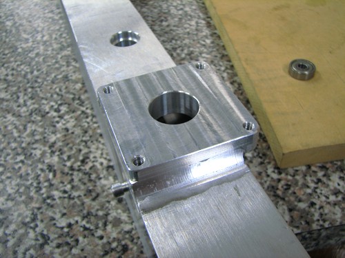
With the internal belts I had to make a couple of blocks for the various pulleys, bearings & shafts to mount to.
The picture shows one side of the cross rail machined to take the blocks (which are the solid bits laying beside it). The little square piece of plate is for the motor to mount to.
IMG_1958.JPG
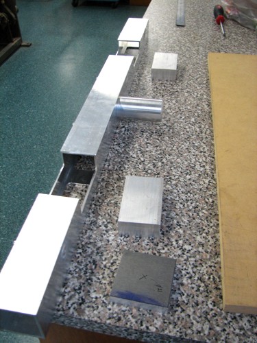
IMG_1958.JPG (69.93 KiB) Viewed 15559 times
And the other side of the rail with the access holes machined in it. These will eventually have a removable cover plate over them to tidy things up on the finished instrument.
IMG_1959.JPG
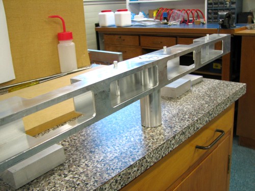
IMG_1959.JPG (68.56 KiB) Viewed 15559 times
The bearing blocks were machined to lighten things up then welded into their respective places on the cross rail. I machined the bores e.t.c after welding just to avoid any distortion, they needed to be a good fit for the bearings!
IMG_1962.JPG
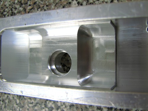
IMG_1962.JPG (49.17 KiB) Viewed 15559 times
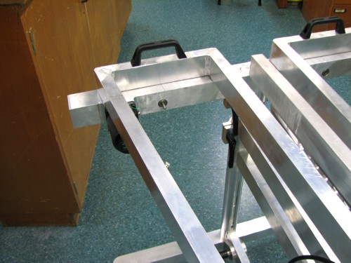
The motor mounting plate was also welded on & the various holes machined in that.
IMG_1961.JPG
IMG_1961.JPG (61.91 KiB) Viewed 15559 times
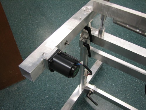
And with the motor mounted
IMG_1965.JPG
IMG_1965.JPG (61.44 KiB) Viewed 15559 times
Once the bar frames are sitting on the top, the motor sits underneath the front frame & becomes relatively inconspicuous :roll:
IMG_1969.JPG
IMG_1969.JPG (60.21 KiB) Viewed 15559 times
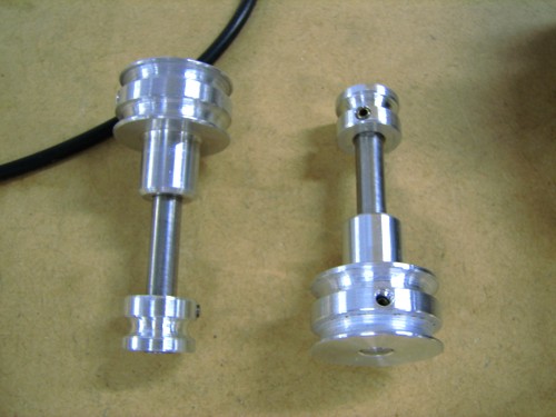
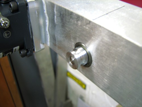
I then turned up some pulleys for the belts to run on, the first closest to the motor has to have allowance for two belts to run on, one from the motor & one over to the other set of resonators but I figured whilst I was set up for machining the two groove I'd make both pulleys the same.So the double pulley sits inside the rail & the single will be the driver for the fan shaft.
IMG_1977.JPG
IMG_1977.JPG (47.03 KiB) Viewed 15559 times
I also had to make a longer pulley for the motor, the factory supplied one was about 15mm long & wouldn't be long enough to fit inside the rail & run inline with my other pulley. Here's a pic showing all the drive bits before being mounted on the rail.
IMG_1976.JPG
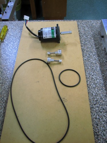
IMG_1976.JPG (60.74 KiB) Viewed 15559 times
Then assembled in the rail. The locating spigot I have in the centre has enough clearance for the belt to run between it & the sidewall of the rail. I could probably go down an O ring size on each part but didn't want to induce too much load on the motor, it's a variable speed AC motor but at it's lower speed setting the torque drops off quite dramatically so I didn't want to either have it stopping at the lower speed or smoking up because of the drag/loading on it from the tight belts. This whole system has to be relatively drag free & quiet!
IMG_1979.JPG
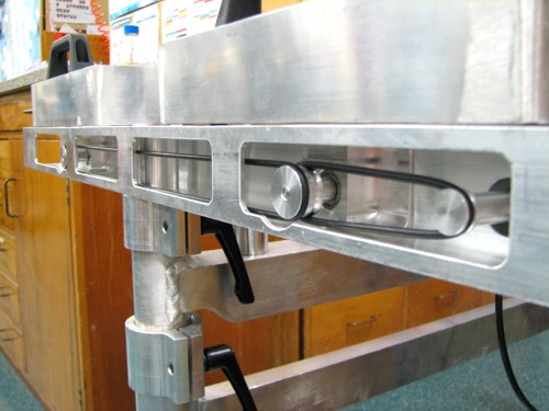
IMG_1979.JPG (56 KiB) Viewed 15559 times
and the appearance from the outside.
IMG_1974.JPG
IMG_1974.JPG (40.31 KiB) Viewed 15559 times
I'm now in the middle of trying to fit the variable speed controller on, the factory unit just didn't sit right so I've "de-housed" it & am currently nutting out the best way to locate & mount it.
"Jesus Loves You."
Nice to hear in church but not in a Mexican prison.

User avatar
Nick
Blackwood
Posts: 3642
Joined: Thu Feb 26, 2009 11:20 am
Location: Christchurch, New Zealand
Contact:

Re: And now for something completely different

Post by Nick » Wed Aug 17, 2011 12:11 pm

It's been a while since I've posted on this build but things have been happening, just slowly :oops:
With the electrical stuff going onto the vibes, my customer understandably wanted a minimum of cabling runs & bits 'hanging' off the vibes so that when he broke it down he didn't need to wrap meters of cabling up with it. I initially made a small sheet metal box to house the control circuitry which I fitted infront of the motor & was mounted to the cross rail. Because the motor system was designed for an American instrument it was 115V so I had also bought a stepdown transformer in a plastic housing, which needed to go on to the vibes somewhere too. I wasn't happy the length of cabling I would need to run to the transformer (I'd planned on fixing this to the foot rail) & also once built, I didn't like the "bolted on" appearance of my controller housing so I had a major re-think. The sheet metal box ended up in the bin & I scratched around in our scrap pile & found a nice bit of Aluminium Channel (Must have been pretty old as the sizing was imperial!) & started from there. I broke open the plastic transformer housing & removed the transformer & managed to mount this beside the circuit board. I removed the external controls that were originally mounted on the circuit board (on/off switch, power LED & the variable speed pot) & mounted these to a seperate bit of vero board so they could be mounted anywhere. I also included an IEC plug receptacle so now the whole control/power unit is in one removable package which mounts to the end of the cross rail in front of the motor, it now just needs the one extension lead to be run out to it. I was able to shape things to fit within the 'look' of the vibes which sat easier in my head too, the original box did look like it was out of place & just thrown on the vibes.
I welded a plate in the end of the cross rail which had a couple of locating pins & a tapped hole in it so removing the whole assembly is just a matter of undoing one screw & sliding the unit off of the locating pins.
Here's everything crammed into the 'housing'
IMG-1996.jpg
IMG-1996.jpg (69.89 KiB) Viewed 15479 times
The lid unscrews to allow access to an inline fuse & the mounting screw. The transformer sat a little high in the frame once I'd put sponge packing around it so I made an additional 'lid' which was mounted on the cover which provides a small vent slot in the bottom edge to provide a through flow of air through the unit to help get rid of any excess heat that may build up in the housing, I will also get a label made up that will sit in the 'well' I made in the vent cover, just to pretty things up a bit & make it look a bit less industrial.
Here's a front on shot of how it looks, I've just quickly scrawled on the front with pen (hence the rough handwritten look!) the fan speed graduations, once everything has been powder coated I'll do these a little more 'professionally'. :wink:
IMG-1999.jpg
IMG-1999.jpg (49.61 KiB) Viewed 15479 times
The plug socket exits from underneath & a right angled plug plugs in, I decided to use a right angled plug to reduce the chance of somebody stepping on the lead & pulling the plug out! (you get the hang of building in a bit of 'idiot proof-ness' when building gear for students! They can destroy anything unintentionally :lol:)
IMG_2000.JPG
IMG_2000.JPG (50.71 KiB) Viewed 15479 times
One more with a few bars sitting on the frame, what is not so visible from the picture is that the control unit sits flush with the ends of the graduated bars so doesn't 'stick out' but fits within the lines of the vibe.
IMG_1992.jpg
IMG_1992.jpg (68.85 KiB) Viewed 15479 times


That's where I'm at so far, I'm in the middle of something I hate..production work!! I've got 90 holders to make to support the hooks that hold the strings which support the bars. I think if I get any more orders for one of these things this is one part of the job I'll definitely be getting made by a CNC company!
"Jesus Loves You."
Nice to hear in church but not in a Mexican prison.

User avatar
Kim
Admin
Posts: 4376
Joined: Wed Sep 26, 2007 8:32 pm
Location: South of Perth WA

Re: And now for something completely different

Post by Kim » Wed Aug 17, 2011 4:34 pm

Great work Nick. 8)

Very clever amalgamation of the electrics. When she's all done and dusted the only thing that will out strip the appeal of that slick pro polished, custom shop form, will be the function. So yes indeed this vibe should be a real eye catcher, but comprehensively though out function is a huge draw card for anyone who has the funds to consider looking at a custom built 'anything'. So my feeling is that you had better enjoy building these things mate because once the word is out there and other serious vibe players get to see the detail of what's under the bonnet, your going to be a making quite a few more of them....After watching the progression in this thread, I want one. I have no interest in ever playing the bloody thing mind...but I do know a bloody good thing when I see it :lol:

Cheers

Kim

User avatar
charangohabsburg
Blackwood
Posts: 1818
Joined: Sat Oct 16, 2010 1:25 am
Location: Switzerland

Re: And now for something completely different

Post by charangohabsburg » Thu Aug 18, 2011 6:31 am

Cable salad has no chance when Nick shows up! :cl
Nick wrote:The sheet metal box ended up in the bin
You should have sold it on eBay! :lol:

I have to say (again? Don't remember. I'm getting old and too lazy to revise what I have written so far) : I enjoy every single update of this vibe-build-thread.
The only downside is that I am starting to doubt if you ever again will build a wooden guitar! :roll: :?:
Markus

To be stupid is like to be dead. Oneself will not be aware of it.
It's only the others who suffer.

User avatar
Nick
Blackwood
Posts: 3642
Joined: Thu Feb 26, 2009 11:20 am
Location: Christchurch, New Zealand
Contact:

Re: And now for something completely different

Post by Nick » Thu Aug 18, 2011 11:11 am

charangohabsburg wrote:I am starting to doubt if you ever again will build a wooden guitar! :roll: :?:
Wood? What's that stuff?? :wink:
I sure hope so Markus, I've got a stack of tonewood here that's begging to be turned into guitars.
"Jesus Loves You."
Nice to hear in church but not in a Mexican prison.

simso
Blackwood
Posts: 1768
Joined: Mon Apr 25, 2011 10:36 pm
Location: Perth WA

Re: And now for something completely different

Post by simso » Thu Aug 18, 2011 3:01 pm

Some quality machine work showing through there mate.

Well done
Steve
Master of nothing,

Do your own repairs - http://www.mirwa.com.au/How_to_Series.html

User avatar
Nick
Blackwood
Posts: 3642
Joined: Thu Feb 26, 2009 11:20 am
Location: Christchurch, New Zealand
Contact:

Re: And now for something completely different

Post by Nick » Thu Aug 18, 2011 6:16 pm

simso wrote:Some quality machine work showing through there mate.

Well done
Thanks Steve, after 32 years of engineering I think I'm just starting to get the hang of it :wink: Depends whether it's a Monday or not though :lol: .
"Jesus Loves You."
Nice to hear in church but not in a Mexican prison.

User avatar
DarwinStrings
Blackwood
Posts: 1877
Joined: Thu Nov 13, 2008 10:27 pm
Location: Darwin

Re: And now for something completely different

Post by DarwinStrings » Thu Aug 18, 2011 8:29 pm

loving all that shiny metal you are doing there Nick and now you have added that pcb that comes along with the box that has a dial. What can i say other than try to talk you into leaving the hand written levels on the dial, I like that bit of rough amongst all the precision.

Jim
Life is good when you are amongst the wood.
Jim Schofield

User avatar
Craig
Admin
Posts: 1090
Joined: Wed Sep 26, 2007 10:08 am
Location: N.S.W. in the bush

Re: And now for something completely different

Post by Craig » Fri Aug 19, 2011 7:42 am

:shock: Awesome work as usual Nick . I remember being blown away by your Maccaferri build , and now this,,,,, way too cool mate .

Bravo :cl
Craig Lawrence

User avatar
kiwigeo
Admin
Posts: 10596
Joined: Sat Sep 29, 2007 5:57 pm
Location: Adelaide, Sth Australia

Re: And now for something completely different

Post by kiwigeo » Sat Aug 20, 2011 2:20 pm

Hey Nick,

Can you do me Vibraphone in Kermit Green? :mrgreen:
Martin

User avatar
Nick
Blackwood
Posts: 3642
Joined: Thu Feb 26, 2009 11:20 am
Location: Christchurch, New Zealand
Contact:

Re: And now for something completely different

Post by Nick » Tue Oct 11, 2011 10:43 am

Well it seems like an eternity since I've posted any progress on this (& you thought I hadn't done any! :oops: ), truth is I've had to take 3 weeks accrued leave from work (had too much accrued & got a telling off :shock: ) plus I've been making loads of the exact same item for this, namely 90 holders for the bar hooks (which I had laser cut from 3mm thick Stainless sheet), so there hasn't been much "visible" progress. I hate production work (stems from weeks at a time of it during my apprenticeship) so didn't enjoy this stage of the job but it was all a means to an eventual end so stuck at it. If I ever make any more of these things this is another item that will be 'contracted' out.
The bars are supported by cord which in turn is supported by the bar hooks. I'm not sure how the commercial units carry out this part of the build but the design I came up with had to have 'sockets' to hold the hooks which are welded into the frame rails. The hooks are designed such that they drop down into a slot in the socket & a 90 degree turn stops them coming out & a grub screw is tightened from underneath which locks everything up & in place.
Here's a picture to show what I'm trying to explain. The 'socket' in this picture is just a blank I machined then cut open to see that I had enough clearance before I began repeating any mistakes on the 90 real ones!
IMG_2050.JPG
IMG_2050.JPG (73.04 KiB) Viewed 15237 times
And when the hook is in place.
IMG_2051.JPG
IMG_2051.JPG (71.37 KiB) Viewed 15237 times
Here's a picture of the individual items that go to make one complete assembly before welding the socket in place on the frame.
IMG_2048.JPG
IMG_2048.JPG (75.68 KiB) Viewed 15237 times
and a shot of the 'loading' slot
IMG_2049.JPG
IMG_2049.JPG (41.45 KiB) Viewed 15237 times
So the hook drops down through the slot and a quarter turn either way has the hook in place, then it's just a matter of nipping up the grub screw to lock everything in.
IMG_2052.JPG
IMG_2052.JPG (51.6 KiB) Viewed 15237 times
The holes for the 'sockets' in the bar frames have to be drilled at several different & decreasing centres to match the graduated widths of the bars.
IMG_2054.JPG
IMG_2054.JPG (65.03 KiB) Viewed 15237 times
I then welded the sockets into the frame from the underside, here's a picture with a few in place, I didn't weld them all in at once, just a few at a time from either end of the frame, in order to avoid distortion of the frame I've been trying to keep straight so far! This approach seemed to work as after welding them all in it's stayed remarkably straight.
IMG_2056.JPG
IMG_2056.JPG (51.46 KiB) Viewed 15237 times
.
This frame (the one I've pictured) holds all the natural notes & the sharps frame is virtually the same as this so I won't bore you by showing that one! I'm varying my approach slightly from that of Jim McCarthy's in that he tunes the bars first then drills the holes through them at the nodal points, for the cord to go through, I've decided to drill the holes first then tune them later. Sean (a new member here) is building his guitar in the shop so I didn't think he'd appreciate me grinding out Aluminium on the belt sander while he's doing his guitar! So I'll do that when he's finished all he needs to do (which isn't too far away). In the meantime I've strung a cord up on the frame and sat the bars on the cord just to check that the cord runs through these nodal points, 5mm each side of these points & the bar seems to loose all of it's sustain & no doubt affect the overtones, but fortunately everything seems to have worked out ok so far!
Attachments
IMG_2052.JPG
IMG_2052.JPG (51.6 KiB) Viewed 15237 times
Last edited by Nick on Tue Oct 11, 2011 10:47 am, edited 1 time in total.
"Jesus Loves You."
Nice to hear in church but not in a Mexican prison.

User avatar
Nick
Blackwood
Posts: 3642
Joined: Thu Feb 26, 2009 11:20 am
Location: Christchurch, New Zealand
Contact:

Re: And now for something completely different

Post by Nick » Tue Oct 11, 2011 10:46 am

Ok, not sure why that picture at the end has doubled up! Hasn't shown up as an attachment in the preview :? Might need a mod to check it out & remove the extra double up.
"Jesus Loves You."
Nice to hear in church but not in a Mexican prison.

User avatar
Craig
Admin
Posts: 1090
Joined: Wed Sep 26, 2007 10:08 am
Location: N.S.W. in the bush

Re: And now for something completely different

Post by Craig » Tue Oct 11, 2011 12:01 pm

Really coming together now Nick ,and looking fantastic as usual . :cl

Had no luck removing the doubled up last Picture sorry mate .
Craig Lawrence

User avatar
kiwigeo
Admin
Posts: 10596
Joined: Sat Sep 29, 2007 5:57 pm
Location: Adelaide, Sth Australia

Re: And now for something completely different

Post by kiwigeo » Tue Oct 11, 2011 2:15 pm

Better be careful when you fire that monster up Nick....you'll probably trigger off a bunch of aftershocks.
Martin

User avatar
Allen
Blackwood
Posts: 5252
Joined: Thu Oct 11, 2007 5:39 pm
Location: Cairns, Australia
Contact:

Re: And now for something completely different

Post by Allen » Tue Oct 11, 2011 7:50 pm

Was just thinking that you should be hard at work on this thing, and there you go. Progress....I'm impressed mate.
Allen R. McFarlen
https://www.brguitars.com
Facebook
Cairns, Australia

User avatar
J.F. Custom
Blackwood
Posts: 779
Joined: Fri May 01, 2009 9:13 pm
Location: Brisbane
Contact:

Re: And now for something completely different

Post by J.F. Custom » Tue Oct 11, 2011 8:09 pm

So Nick, how many arms and legs will you have in stock once you complete this art piece ???

Sensational. 8)

Oh, and my wife wants one... "Pretty please" she said. :roll:

I've told her I think it may be worth a few ukes to trade... :lol:

Jeremy.

User avatar
charangohabsburg
Blackwood
Posts: 1818
Joined: Sat Oct 16, 2010 1:25 am
Location: Switzerland

Re: And now for something completely different

Post by charangohabsburg » Tue Oct 11, 2011 8:19 pm

Impressive as usual!
Nick wrote:The hooks are designed such that they drop down into a slot in the socket & a 90 degree turn stops them coming out &
I'm looking forward to see the finished instrument in order to understand why you not just welded in a bent wire. :lol:
Markus

To be stupid is like to be dead. Oneself will not be aware of it.
It's only the others who suffer.

User avatar
Clancy
Blackwood
Posts: 620
Joined: Wed Dec 17, 2008 10:26 am
Location: Canberra

Re: And now for something completely different

Post by Clancy » Tue Oct 11, 2011 8:42 pm

I'm looking forward to see the finished instrument in order to understand why you not just welded in a bent wire.
Um....yeah? :? ?
Craig
I'm not the sharpest tool in my shed

User avatar
charangohabsburg
Blackwood
Posts: 1818
Joined: Sat Oct 16, 2010 1:25 am
Location: Switzerland

Re: And now for something completely different

Post by charangohabsburg » Wed Oct 12, 2011 2:27 am

Clancy wrote:
I'm looking forward to see the finished instrument in order to understand why you not just welded in a bent wire.
Um....yeah? :? ?
Yeah. Of course a sturdy high tech wire, maybe of titanium, one of those they use in NZ for monstersheep fences ;). Or also a welded solid machined rigid hook if you like this more. But at the moment I don't grab it why it must be 90°-turnable and removable.
Markus

To be stupid is like to be dead. Oneself will not be aware of it.
It's only the others who suffer.

Post Reply

Who is online

Users browsing this forum: No registered users and 287 guests