Not much 'major' movement on the vibes last week,appearance wise, but I was busy, it's amazing how much time the little fiddly bits can take!

I've been working on the resonator fan's drive system. The motors are usually mounted at the narrow end (less distance for a belt to run I guess) but as I have the damper mechanism where it is there's no real room up there to mount the motor so after checking with the customer, in the wide end it goes! I decided to mount the belts inside the cross rail just so things look abit tidy but I still need to provide access for belt changes. The belts aren't really belts, they're readily available O rings but I will provide the customer a couple of spares for Justin.
With the internal belts I had to make a couple of blocks for the various pulleys, bearings & shafts to mount to.
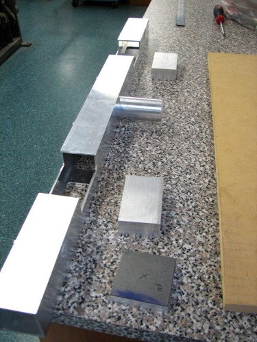
The picture shows one side of the cross rail machined to take the blocks (which are the solid bits laying beside it). The little square piece of plate is for the motor to mount to.
- IMG_1958.JPG (69.93 KiB) Viewed 18727 times
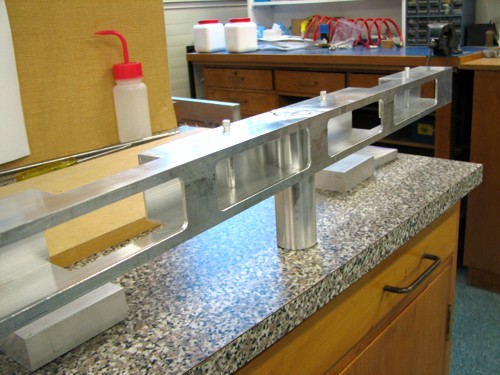
And the other side of the rail with the access holes machined in it. These will eventually have a removable cover plate over them to tidy things up on the finished instrument.
- IMG_1959.JPG (68.56 KiB) Viewed 18727 times
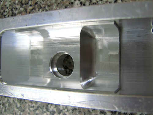
The bearing blocks were machined to lighten things up then welded into their respective places on the cross rail. I machined the bores e.t.c after welding just to avoid any distortion, they needed to be a good fit for the bearings!
- IMG_1962.JPG (49.17 KiB) Viewed 18727 times
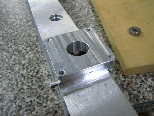
The motor mounting plate was also welded on & the various holes machined in that.
- IMG_1961.JPG (61.91 KiB) Viewed 18727 times
And with the motor mounted
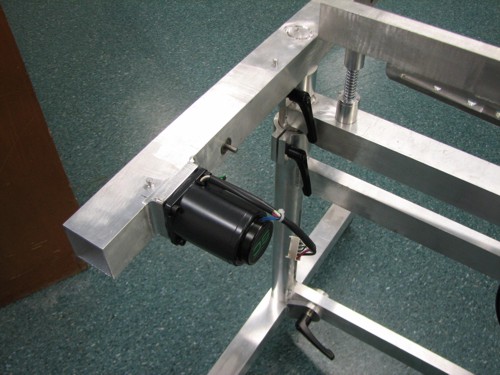
- IMG_1965.JPG (61.44 KiB) Viewed 18727 times
Once the bar frames are sitting on the top, the motor sits underneath the front frame & becomes relatively inconspicuous

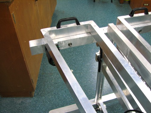
- IMG_1969.JPG (60.21 KiB) Viewed 18727 times
I then turned up some pulleys for the belts to run on, the first closest to the motor has to have allowance for two belts to run on, one from the motor & one over to the other set of resonators but I figured whilst I was set up for machining the two groove I'd make both pulleys the same.So the double pulley sits inside the rail & the single will be the driver for the fan shaft.
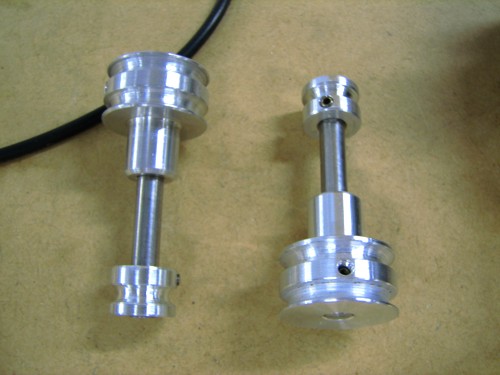
- IMG_1977.JPG (47.03 KiB) Viewed 18727 times
I also had to make a longer pulley for the motor, the factory supplied one was about 15mm long & wouldn't be long enough to fit inside the rail & run inline with my other pulley. Here's a pic showing all the drive bits before being mounted on the rail.

- IMG_1976.JPG (60.74 KiB) Viewed 18727 times
Then assembled in the rail. The locating spigot I have in the centre has enough clearance for the belt to run between it & the sidewall of the rail. I could probably go down an O ring size on each part but didn't want to induce too much load on the motor, it's a variable speed AC motor but at it's lower speed setting the torque drops off quite dramatically so I didn't want to either have it stopping at the lower speed or smoking up because of the drag/loading on it from the tight belts. This whole system has to be relatively drag free & quiet!
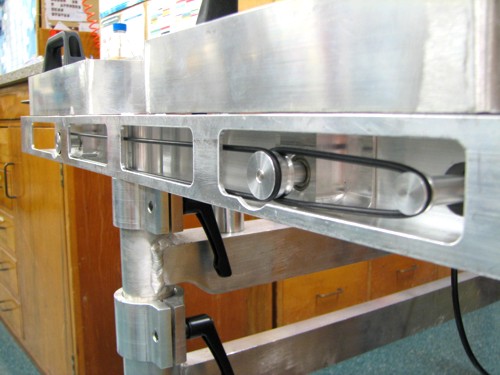
- IMG_1979.JPG (56 KiB) Viewed 18727 times
and the appearance from the outside.
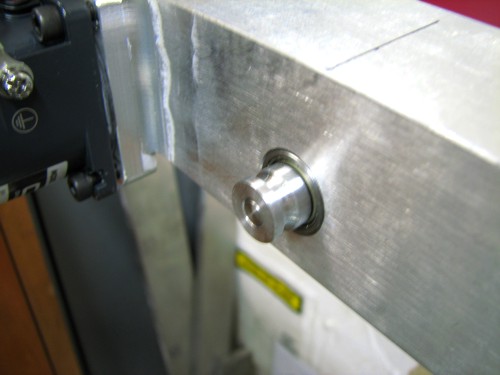
- IMG_1974.JPG (40.31 KiB) Viewed 18727 times
I'm now in the middle of trying to fit the variable speed controller on, the factory unit just didn't sit right so I've "de-housed" it & am currently nutting out the best way to locate & mount it.