Well due to the long weekend we had with the 'official' regal birthday & various other matters I haven't progressed much with this project over the past couple of weeks so it's slim pickens (not the star of Blazin' Saddles either!) in this post but was getting into 'making the pedal' stage when things were curtailed by mother nature again & the uni's been shut until the engineers can get around to inspect the buildings! So I thought I'd take the opportunity to update this build to where I'm at.
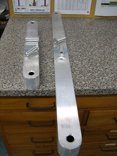
I had done the feet so it's fully mobile now. I bushed the 50X50 box section ally so the wheels had something 'substantial' to screw into, I used recoils on the threads again just so the mountings were strong & didn't rip the bolts out if ever the wheels were to hit anything (such as a small step or ledge), I also radiused & capped the ends just to make them look more a bit prettier

- IMG_1890.JPG (166.97 KiB) Viewed 20273 times
Once the bushes were welded in I dressed the welds to make them invisible once the paint goes on. I wanted to design the whole instrument so that it could be taken apart & become a 'flat pack' similar to Bunning's DIY kitchens!

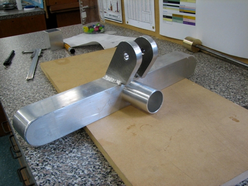
So that meant making the feet removeable but be able to be easily re-assembled & located in the correct position each time. To do this I used the two things I had available at the bottom of each frame, the down tube & the cross rail. I put a tube that was the right size to fit inside the downtube, right through the square box section (putting it in double shear & therefore stronger than just welding it to one face), that took care of the 'fore & aft' location then I cut some 'lugs' from the 12mm plate I'd got for the bars & sundry items such as these lugs & the foot pedal. These lugs took care of the positioning of the feet in a 'rotary' axis, they also act as clamps to hold the whole thing on by threading & recoiling the rear lug so a bolt (or clamping handle I have for the finished item) could go through the whole assembly & clamp the lugs to the crossbar.
- IMG_1896.JPG (159.7 KiB) Viewed 20273 times
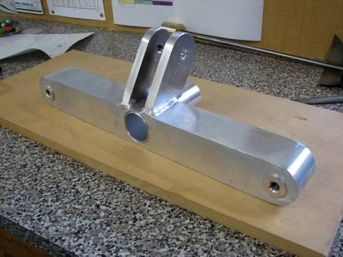
- Down tube hasn't been welded in this shot.
- IMG_1895.JPG (168.17 KiB) Viewed 20273 times
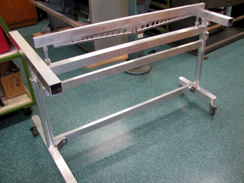
And here's a picture of the feet back on the frame, the top frame supports (which will eventually locate & support the bar frames) have just been sat on the top to get the idea of what the main frame will look like.
- IMG_1898.JPG (178.09 KiB) Viewed 20273 times
Next up I had to move onto the foot pedal in order to complete the main frame. I decided early on that with the ability to alter the height adjustment I needed an easy way to alter the link between the pedal & the damper bar. Commercial units have a rod inside a tube which is clamped in place via a wing nut, but rather than fiddling around on the floor doing up wing nuts everytime it's either assembled or adjusted, it would be easier just to use a Bowden cable as my link (think car's throttle cable with a wire running inside a sleeve). This way it can stay 'as it is' & just move up & down with the frame & also caters for the other design hankering I had for making the footpedal adjustable along the length of the bottom cross bar. That way if ever a left footer had a go on it, it's just a matter of loosening off a clamp handle & sliding the pedal over to the left side of the instrument, or even if the same player wanted to adjust where the footpedal felt 'most comfortable'.
With a rough length of cable that I wanted, in my head, it was off down to the local motorcycle spares shop & after rummaging through his collection I found a Honda XR250 throttle cable that fit the bill nicely

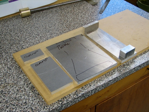
I've cut some more plate up that will go to make the various components to the footpedal.
- IMG_1904.JPG (182.36 KiB) Viewed 20273 times
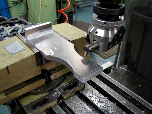
I started with the main bracket that will hold the pedal & clamp everything together. I've welded on a piece that forms the top plate & decided to do a bit of shaping to lighten things up a bit & also give it a more interesting shape than just a rectangle! I rough cut a radius in the sides with the bandsaw then used the boring head clean up the cut.
- IMG_1905.JPG (172.27 KiB) Viewed 20273 times
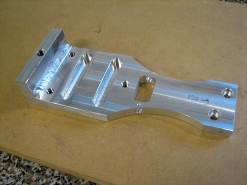
And the finished article
- IMG_1907.JPG (139.77 KiB) Viewed 20273 times
The various holes & slots will become apparent as I go so I won't get all tied up describing them at this stage!(thank goodness I here you say

)
I was halfway through making the clamping part of the pedal when the earthquake hit & we had to evacuate so that's where I'm currently at until we can get back into the building, which will hopefully be tomorrow.


Yeah an airship will be further down the track, will have to build an extension on the shed first to fit one of them babies in!