Project PIG the F1-11 'Matey'

Hey Nick thanks for the encouragement my friend but I am under no illusion, I know that this will never be a truly great guitar. But that's OK because 'great' is not what I have set out to achieve. What I hope to gain from this project is a really 'good' guitar, one that is very comfortable to hold and play yet sounds pretty good as well. The sort of guitar that will have that look and mojo which 'makes' you pick it up and play the bloody thing. A veranda guitar to share around while drinking a few coldies with good mates, and when you need to stop and siphon the python, you can rest it against the wall for a while without having to dance around like a cheery bugger for fear of it falling over.
The fact that this guitar left the factory as a narrow bodied plywood classical with a heelless neck converted to a steel string kind of plays toward that goal. Ply is quite resilient, and the narrow sided body quite comfortable to hold, to top it off the planned 24.9" Martin short scale should make it nice and easy for comfy barre chords as well.
The fact that this guitar left the factory as a narrow bodied plywood classical with a heelless neck converted to a steel string kind of plays toward that goal. Ply is quite resilient, and the narrow sided body quite comfortable to hold, to top it off the planned 24.9" Martin short scale should make it nice and easy for comfy barre chords as well.
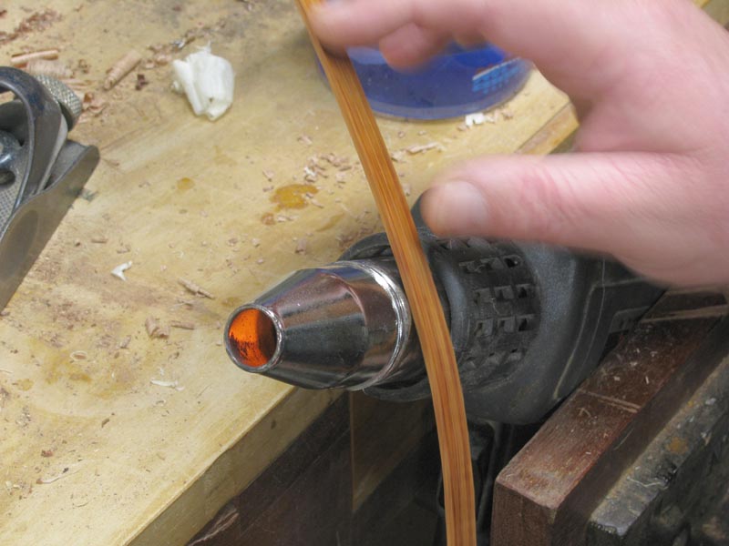
I looked around and found some tassie oak and un-figured blackwood off cuts that would make suitable solid linings. I did not have enough 'scrap' that was long enough to allow me to saw multiple thin lamination and cold glue them using the guitar body as a form. So the only option was to leave what I had quite thick and soak them in the bath ( yes, she did) before starting the bending process by hand.
I sat down and turned on the gas and then pulled my top lip over the bottom as I realise the long out of date bottle was now finally empty. Buy a new gas bottle, or use the collar of paint strip gun

>
>
>
>
>
>
>
>
>
>
>
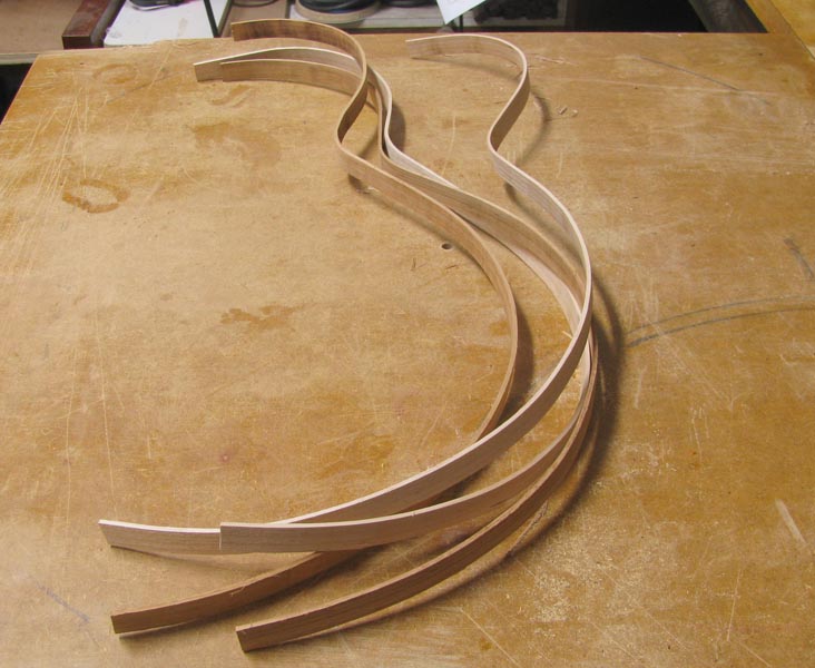
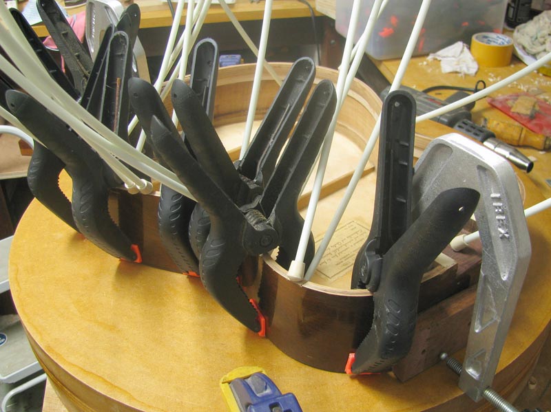
A while latter and where set to go, at least for the top edge anyhow:
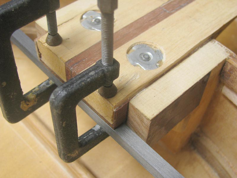
Once again epoxy was used, Smith's Allwood, because gaps like this are difficult to avoid in this situation......(For anyone wondering about my dramatic sensitivity issues with epoxy, all I can tell you is that I have been told that when I use the stuff now days and am dressed in my full body tyvek suit, respirator, thick gloves and barrier cream, I resemble some sort of manic teli tubby on roids)
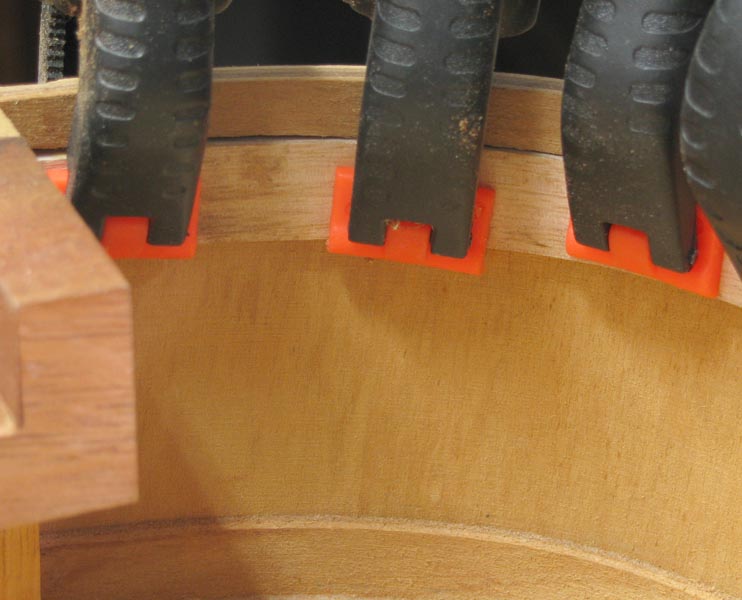
But not really an issue if you have lots and lots of those cheap Chinese spring clamps. My advise, buy a few bags and chuck out any that feel weak and they are wonderful
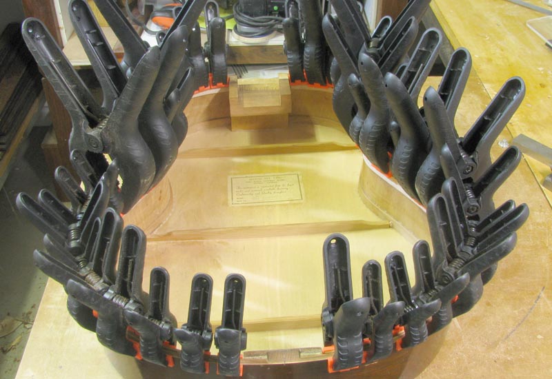
Bit of a scrape and sand...
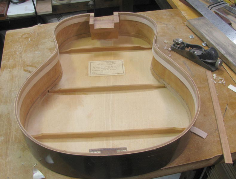
And with the first liners in, and the tailblock and neckblock extension done, shes start'in to look'in alright.
More later.........
I sat down and turned on the gas and then pulled my top lip over the bottom as I realise the long out of date bottle was now finally empty. Buy a new gas bottle, or use the collar of paint strip gun
>
>
>
>
>
>
>
>
>
>
>
A while latter and where set to go, at least for the top edge anyhow:
Once again epoxy was used, Smith's Allwood, because gaps like this are difficult to avoid in this situation......(For anyone wondering about my dramatic sensitivity issues with epoxy, all I can tell you is that I have been told that when I use the stuff now days and am dressed in my full body tyvek suit, respirator, thick gloves and barrier cream, I resemble some sort of manic teli tubby on roids)
But not really an issue if you have lots and lots of those cheap Chinese spring clamps. My advise, buy a few bags and chuck out any that feel weak and they are wonderful
Bit of a scrape and sand...
And with the first liners in, and the tailblock and neckblock extension done, shes start'in to look'in alright.
More later.........
Beautiful work Kim my friend and a most interesting thread too!
I don't know but I have a feeling that even though as you said you don't have the highest expectations for what this great guitar will be when completed it may surprise you and you may find it to be one of your favorite players once completed.
Great thread, superb craftsmanship - thanks for sharing.
Thanks Hesh 
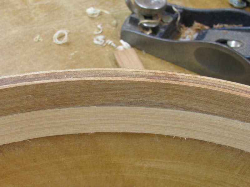
By repeating this treatment for the top edge, the original and under linings are locked together which makes the rims MUCH stiffer and there is now enough meat to rout the binding ledge and leave behind enough material to securely glue the top to the rims.
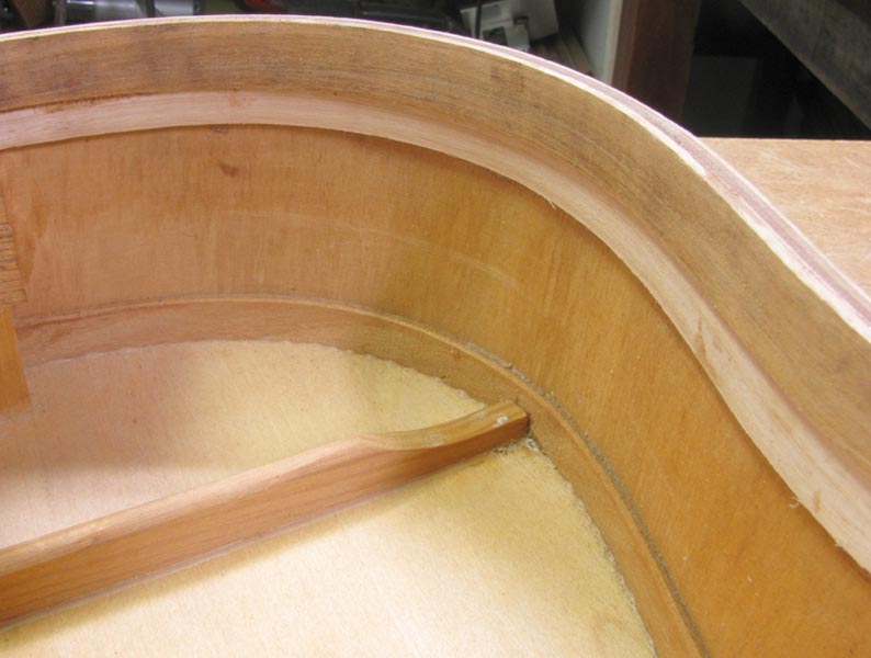
With that cleaned up it was off to the 25' radius dish again to do a quick final sanding of the radius into the top rim. Then a couple of spruce veneers were glued to the top edge of the neck block and it was off to the flat sanding board where a 1/8" spacer was taped to the tailblock to lift the lower bout clear whilst the upper bout rim from the UTB forward was flatend into a single plane which would mimic the approximate neck angle of the finished guitar.
Doing this not only makes life much easier to achieve a nice clean fit between the fretboard extension and the top, but it would also help me a great deal in setting out the modified UTB that would eventually support the very back of the heelless neck tenon.
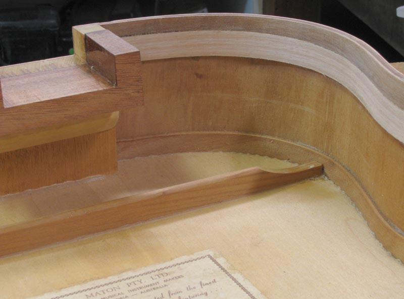
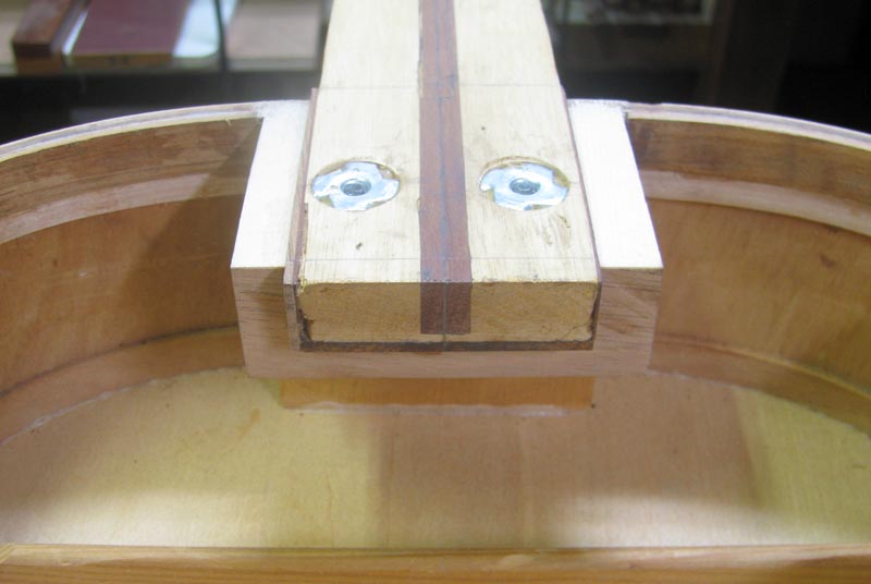
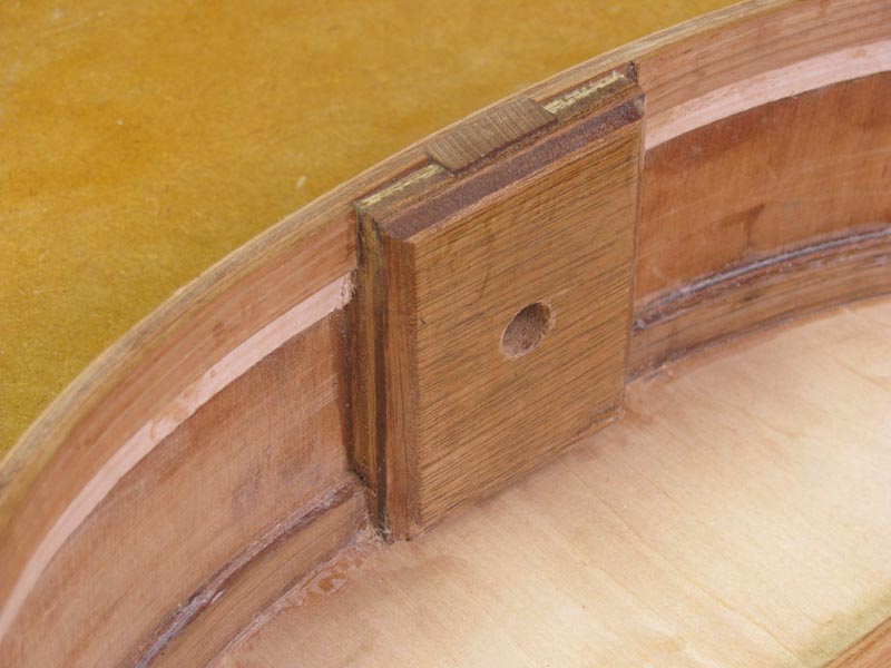
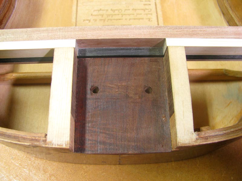
Now with a couple of holes drilled through the neck tenon and neckblock extension, and then a couple of "T" nuts fitted to accept the bolts that will hold the neck on:
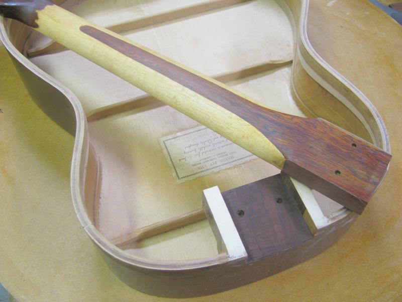
We can finally see the pig starting to come together:
As you can see from this next image, I have shimmed out the tenon to centralise the neck in the mortise. There is a couple of reason I chose to do it this way rather than simply shim the mortise. First the sides of the tenon were damaged in the 'extraction' process and I wanted a nice 'smooth' sliding fit. When this goes together I want to hear the sssshhhhhhhhhh click!!! of good joinery. But also it is much easier to adjust out any skew from the tenon, and finally, to allow for any possible neck angle re-sets, I want to be able to take this joint apart again when the guitar is finished without needing to destroy the bindings planned for the front of the neck pocket. I have an idea that will help me work around this problem and the tenon veneers, although quite thin, will play a role in that.
Anyhow, its on to the top now as it needs to be braced up and let in to the sides so I can work out what I will do to set out the modified UTB. I gotta get this bit right because the modified UTB will work in conjunction with the neckblock extension to set the final neck angle. You may have noticed that I have glued a veneer into the bottom of the neck pocket. This veneer is actually a very thin wedge. It is sacrificial and will be sanded away with a bias toward the front edge to fine tune the neck setting but more on that later.
On with the top! later.........
By repeating this treatment for the top edge, the original and under linings are locked together which makes the rims MUCH stiffer and there is now enough meat to rout the binding ledge and leave behind enough material to securely glue the top to the rims.
With that cleaned up it was off to the 25' radius dish again to do a quick final sanding of the radius into the top rim. Then a couple of spruce veneers were glued to the top edge of the neck block and it was off to the flat sanding board where a 1/8" spacer was taped to the tailblock to lift the lower bout clear whilst the upper bout rim from the UTB forward was flatend into a single plane which would mimic the approximate neck angle of the finished guitar.
Doing this not only makes life much easier to achieve a nice clean fit between the fretboard extension and the top, but it would also help me a great deal in setting out the modified UTB that would eventually support the very back of the heelless neck tenon.
Now with a couple of holes drilled through the neck tenon and neckblock extension, and then a couple of "T" nuts fitted to accept the bolts that will hold the neck on:
We can finally see the pig starting to come together:
As you can see from this next image, I have shimmed out the tenon to centralise the neck in the mortise. There is a couple of reason I chose to do it this way rather than simply shim the mortise. First the sides of the tenon were damaged in the 'extraction' process and I wanted a nice 'smooth' sliding fit. When this goes together I want to hear the sssshhhhhhhhhh click!!! of good joinery. But also it is much easier to adjust out any skew from the tenon, and finally, to allow for any possible neck angle re-sets, I want to be able to take this joint apart again when the guitar is finished without needing to destroy the bindings planned for the front of the neck pocket. I have an idea that will help me work around this problem and the tenon veneers, although quite thin, will play a role in that.
Anyhow, its on to the top now as it needs to be braced up and let in to the sides so I can work out what I will do to set out the modified UTB. I gotta get this bit right because the modified UTB will work in conjunction with the neckblock extension to set the final neck angle. You may have noticed that I have glued a veneer into the bottom of the neck pocket. This veneer is actually a very thin wedge. It is sacrificial and will be sanded away with a bias toward the front edge to fine tune the neck setting but more on that later.
On with the top! later.........
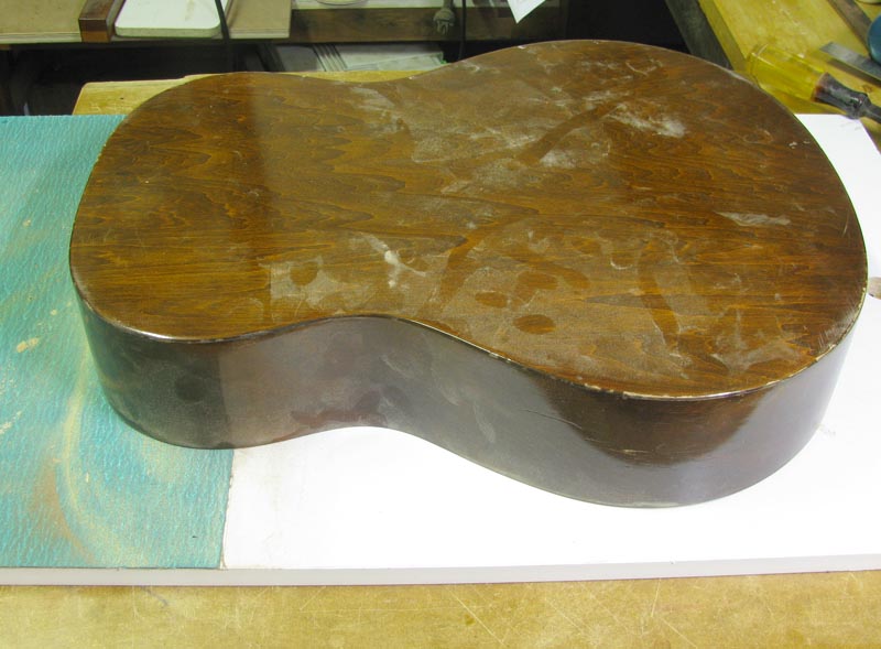
OK, because the top of this guitar is to be stained to give it some age, the top ear marked for use on the pig (there's a saying about pigs ears that could cruelly be used to describe this project but I'll ask the idiot gallery to please refrain ) is a set of beige/latte coloured Lutz. I bought this top in a fit of madness from a dimly lit on-line auction where all the wood has fruity names and everyone takes their chances. Thankfully I did not pay very much for it because when it finally arrived in AU from Canada some 3 month later, I discovered that the edge with the tightest grain count which is the edge traditional used for jointing, had a long waney edge with a little bark still attached.
To remove the bark and true up the edge was not really an option as the plates were supplied at just 7 3/8"
To remove the bark and true up the edge was not really an option as the plates were supplied at just 7 3/8"
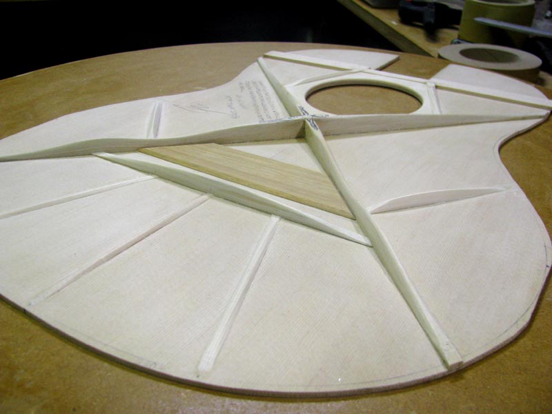
Whoops..............Guess I should have shown the rosette first as this is installed before the soundhole patch but 'before' the actual soundhole is cut.
As mentioned earlier, I wanted to do a traditional Martin style ringed rosette on this guitar to try and capture some of that vintage mojo. As it turns out, I had been sent just the purfling material required to do this as part of the great prize pack I won for my part in designing the logo for The Luthiers Community.
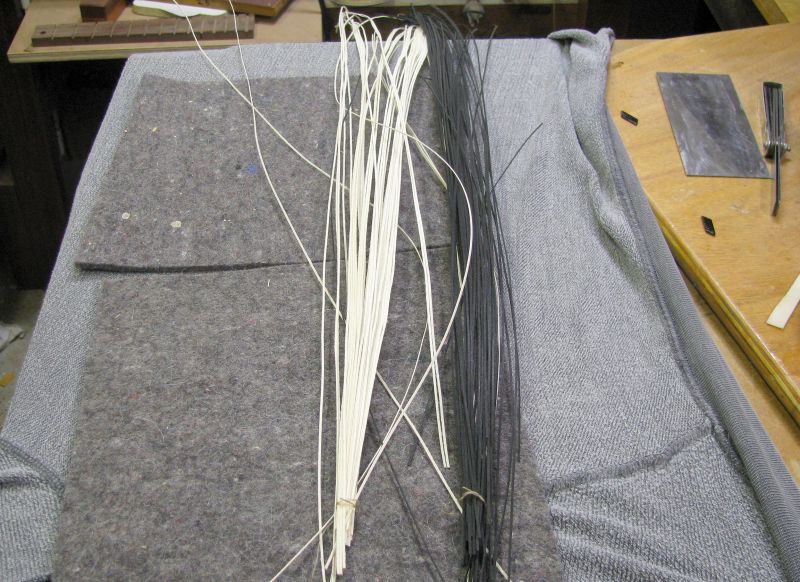
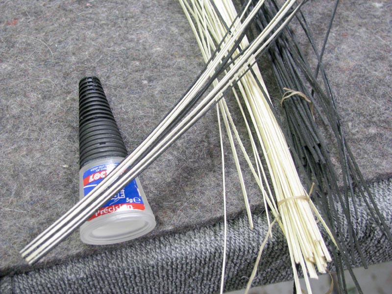
Now I can't tell you for sure exactly what woods this big bunch of purfling was made from, I have assumed the white is Holy, and the black is dyed Maple. A couple of things I can tell you is that it looks really classy, it is great to work with, and it was generously supplied by Grant Goltz along with a stack of other great stuff. I really lucked out with this prize because what Grant donated was then packaged up by our good mate Dennis Leahy who took it upon himself to fill the box with yet more great tonewood from his own stash.
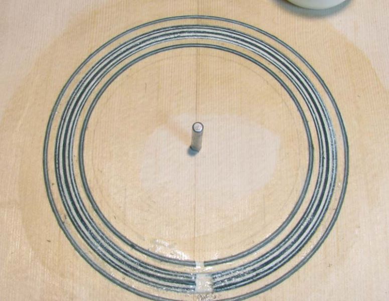
Anyhow this purfling may look as unruly as a bunch of string but it can soon be tamed by stitching the ends together with a bit of CA ready for layout into the rosette channel.
What we have above is 12 strands of purfling tacked up in the following order, B/W/B/WW/BB/WW/B/W/B and these will form the centre ring of the rosette and then standard supply house B/W/B purflings will form the inner and outer rings. The work area of the soundboard is first sealed with super blonde shellac and the rosette channel is cut. The channel is flooded with yellow glue, in this instance Titebond original, and the rosette purflings are fed into the channel and pressed into place.
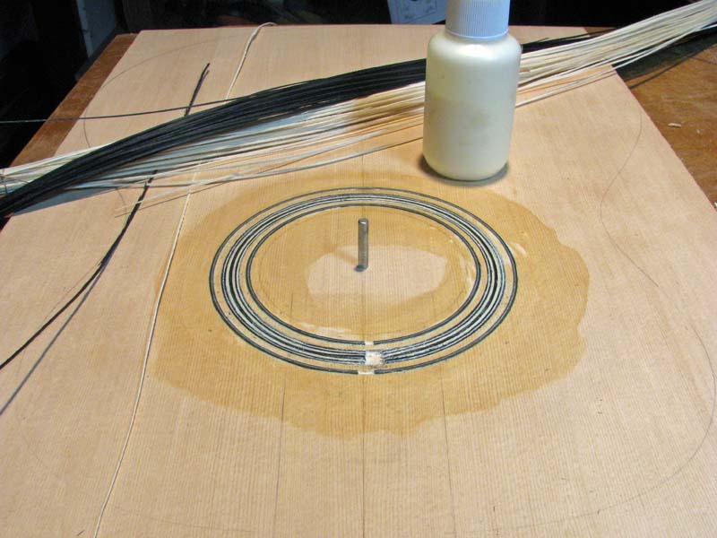
A quick clean-up with a good sharp scraper once dry...
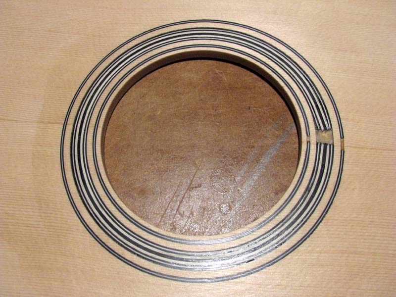
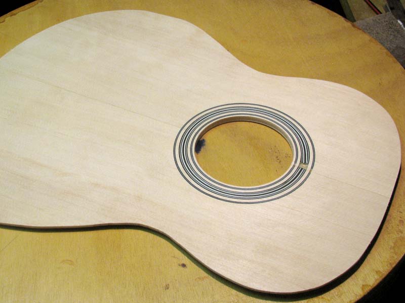
And then wait a while for it to totally cure before sanding to avoid sink back and then we can flip the top over and proceed with the bracing.
Stay tuned.......
As mentioned earlier, I wanted to do a traditional Martin style ringed rosette on this guitar to try and capture some of that vintage mojo. As it turns out, I had been sent just the purfling material required to do this as part of the great prize pack I won for my part in designing the logo for The Luthiers Community.
Now I can't tell you for sure exactly what woods this big bunch of purfling was made from, I have assumed the white is Holy, and the black is dyed Maple. A couple of things I can tell you is that it looks really classy, it is great to work with, and it was generously supplied by Grant Goltz along with a stack of other great stuff. I really lucked out with this prize because what Grant donated was then packaged up by our good mate Dennis Leahy who took it upon himself to fill the box with yet more great tonewood from his own stash.
Anyhow this purfling may look as unruly as a bunch of string but it can soon be tamed by stitching the ends together with a bit of CA ready for layout into the rosette channel.
What we have above is 12 strands of purfling tacked up in the following order, B/W/B/WW/BB/WW/B/W/B and these will form the centre ring of the rosette and then standard supply house B/W/B purflings will form the inner and outer rings. The work area of the soundboard is first sealed with super blonde shellac and the rosette channel is cut. The channel is flooded with yellow glue, in this instance Titebond original, and the rosette purflings are fed into the channel and pressed into place.
A quick clean-up with a good sharp scraper once dry...
And then wait a while for it to totally cure before sanding to avoid sink back and then we can flip the top over and proceed with the bracing.
Stay tuned.......

-
John Maddison

- Blackwood
- Posts: 354
- Joined: Tue Jun 03, 2008 11:15 pm
- Location: Albany, Western Australia
- Contact:
I got my blonde de-waxed shellac at Goods and Chattels John. Terrific service, and very comprehensive selection. I had trouble finding it in their catalogue, so just fired an email off to them, and got a very quick response with pricing and quantities available.
-
Dennis Leahy

- Blackwood
- Posts: 872
- Joined: Wed Oct 10, 2007 12:32 am
- Location: Duluth, MN, US
- Contact:
Thanks folks,
Sorry for the slow progress getting this stuff posted but even though most the images were taken as I went along, I am finding it takes 'much' longer to compile, edit, resize and explain the process than it did to do the actual work.
Hopefully this thread will end up being useful. I have found in the repair side of the craft that the need to work within predetermined design parameters of an already constructed guitar is a lot more challenging than building a guitar from scratch. No fudging here, you need to plan things out so they fit as right as they can from the start, no option of making bit "B" fit bit "A" cause you did not cut "A" correctly on the first go.
Hey Nick,
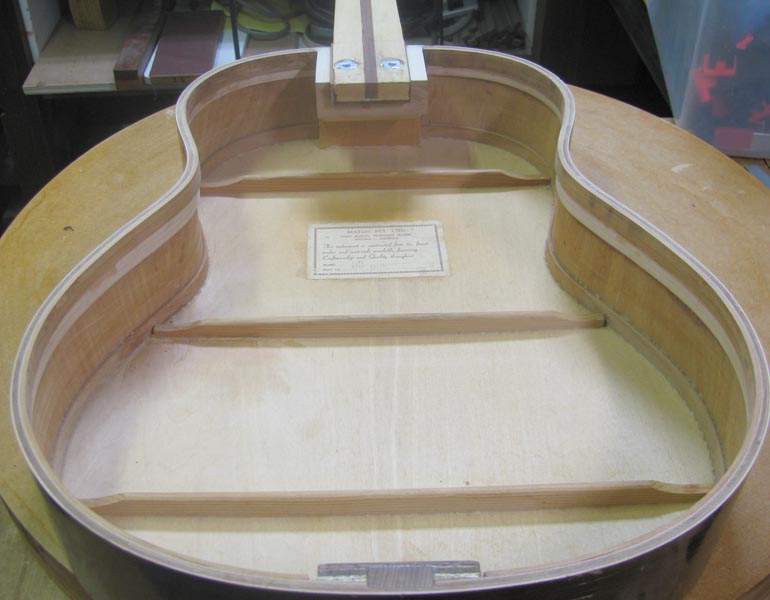
Like most things in lutherie I am certain that a single 'horizontal' tone bar with adjoining fans has been done before, however I had not seen it before I tried it. The design is what I came up with to try and achieve what I am looking for in a top. I had used much the same pattern on my first and it has held up well thus far and am very happy with the sound.
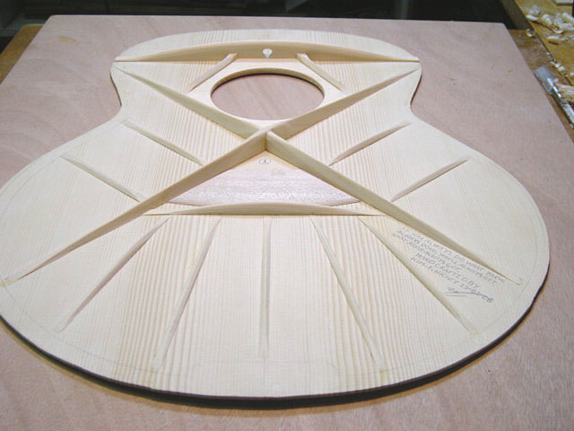
You should notice when comparing the bracing in above image to the that of the F1-11, that the pig has lost two of the fan or distribution veins from behind the bridge plate and also two finger braces. This is just more experimentation, if it can't justify its existence to me, it gets the flick.
In practice my design is simple enough. Strengthen the soundhole area for those reasons already explained and loose the tone bars which, for reasons I have never entirely understood, traditionally angle from the inner surface of the rear treble side leg of the "X" brace from somewhere just behind, and or across the bridge plate, and cross the lower bout between the rear legs of the "X", and replace them with this single 'manifold' brace placed behind the bridge plate.
It is generally understood that as torque created by string tension takes affect upon the bridge/bridge plate area of the top, the bridge will attempt to rotate toward the soundhole. This movement is arrested by the structure of the top itself and that bracing to the front, and also to the rear of the bridge plate.
The aim of my bracing configuration is to transfer more available energy, more evenly into that area of the guitars top which I consider to be the most influential in the production of desirable sound. The theory behind how this bracing configuration will help to achieve this is based upon my belief that the manifold brace will become loaded with torque and direct energy into the adjoining fans or veins which will disperse that energy out evenly into the top between the legs of the lower "X" brace which, at this stage of my lutherical journey, I consider the most valuable area of a guitar top.
With this energy now evenly dispersed across the rear of the top, it is hypothesised that the effect will 'pull' the top into tension to be much like the skin of a drum and therefore more responsive to the dipole action of the bridge which is that movement we know to amplify the sound of an acoustic guitar. I now believe that the efficient transfer of the dipole effect into the top may explain the considerable volume and fast attack or response of my first guitar. What ever it is, it seems to have worked well for me so I have chosen to apply similar to this guitar as I suspect it will need all the help it can get.
Cheers
Kim
Like most things in lutherie I am certain that a single 'horizontal' tone bar with adjoining fans has been done before, however I had not seen it before I tried it. The design is what I came up with to try and achieve what I am looking for in a top. I had used much the same pattern on my first and it has held up well thus far and am very happy with the sound.
You should notice when comparing the bracing in above image to the that of the F1-11, that the pig has lost two of the fan or distribution veins from behind the bridge plate and also two finger braces. This is just more experimentation, if it can't justify its existence to me, it gets the flick.
In practice my design is simple enough. Strengthen the soundhole area for those reasons already explained and loose the tone bars which, for reasons I have never entirely understood, traditionally angle from the inner surface of the rear treble side leg of the "X" brace from somewhere just behind, and or across the bridge plate, and cross the lower bout between the rear legs of the "X", and replace them with this single 'manifold' brace placed behind the bridge plate.
It is generally understood that as torque created by string tension takes affect upon the bridge/bridge plate area of the top, the bridge will attempt to rotate toward the soundhole. This movement is arrested by the structure of the top itself and that bracing to the front, and also to the rear of the bridge plate.
The aim of my bracing configuration is to transfer more available energy, more evenly into that area of the guitars top which I consider to be the most influential in the production of desirable sound. The theory behind how this bracing configuration will help to achieve this is based upon my belief that the manifold brace will become loaded with torque and direct energy into the adjoining fans or veins which will disperse that energy out evenly into the top between the legs of the lower "X" brace which, at this stage of my lutherical journey, I consider the most valuable area of a guitar top.
With this energy now evenly dispersed across the rear of the top, it is hypothesised that the effect will 'pull' the top into tension to be much like the skin of a drum and therefore more responsive to the dipole action of the bridge which is that movement we know to amplify the sound of an acoustic guitar. I now believe that the efficient transfer of the dipole effect into the top may explain the considerable volume and fast attack or response of my first guitar. What ever it is, it seems to have worked well for me so I have chosen to apply similar to this guitar as I suspect it will need all the help it can get.
Cheers
Kim
OK, with the new top of the F1 now braced and ready to go,
(One more from a different angle so you can see how touch and go the width of this top set was...
it was time to clean up the glue squeeze shown earlier, trim the ends from the back braces and then fit and glue in the support linings for the back giving material for a binding ledge, and adding even more stiffness to the sides....
Just a quick check over to tidy up the loose ends, such as cutting a bevel the tail block which should have been done 'before' it was glued in, and then drilling a hole ready for the end pin jack...
and the body of the Matey was finally ready to have the new top let in to its linings. Now with the neck, body, and top all know quantities, it was time to start working out how I would approach the modified UTB.
More tomorah...
-
Joe Sustaire
- Myrtle
- Posts: 92
- Joined: Sun Nov 23, 2008 1:23 am
- Location: Talihina Oklahoma
- Contact:
Hey Kim, thanks for letting us in on the thinking behind your bracing design. To me this is the good stuff, that really makes a difference between a hand-built guitar and a factory job. And as you know I love to explore these different ideas. So don't be surprised if you see these ideas "borrowed" by some backwoods okie.
Thanks,
Joe
Thanks,
Joe
The only safe thing to do, is to take a chance! Mike Nichols
Thanks Joe and Jeff,
Joe,
Feel free to borrow what you need my friend
Jeff,
As mentioned there is already a substantial 45 degree glue block which pretty much works as a buttress uniting the components in such a way as to not restrict access to the bolts or ratchet during fitting and removal of the neck.
In fact the glue block has been shaped in such a way as to help 'guide' the bolts into there respective holes which is handy when working blind in what is a very restricted area. I guess I should have taken more images but sometimes you just keep moving on and forget about it. You will soon see how I over came the issue of support and I am happy with the result even if some do consider it overkill this will be where the CF come in to play and the F1 becomes the F1-11.
Once again please forgive my lack of drafting skills but this image should serve to demonstrate the function of the supportive glue block. We used these an awful lot in stair making and they work very effectively.
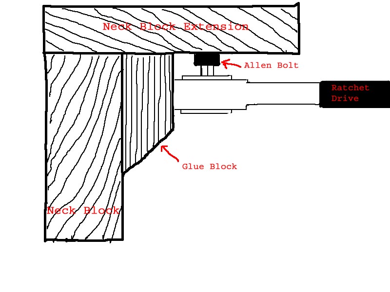
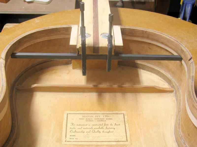
You can actually see part of the glue block visible in this next image..
More soon, Wife's Bday to day so sometime over the weekend.
Cheers
Kim
Joe,
Feel free to borrow what you need my friend
Jeff,
As mentioned there is already a substantial 45 degree glue block which pretty much works as a buttress uniting the components in such a way as to not restrict access to the bolts or ratchet during fitting and removal of the neck.
In fact the glue block has been shaped in such a way as to help 'guide' the bolts into there respective holes which is handy when working blind in what is a very restricted area. I guess I should have taken more images but sometimes you just keep moving on and forget about it. You will soon see how I over came the issue of support and I am happy with the result even if some do consider it overkill this will be where the CF come in to play and the F1 becomes the F1-11.
Once again please forgive my lack of drafting skills but this image should serve to demonstrate the function of the supportive glue block. We used these an awful lot in stair making and they work very effectively.
You can actually see part of the glue block visible in this next image..
More soon, Wife's Bday to day so sometime over the weekend.
Cheers
Kim
Thanks for posting the progress, Kim.
I've got to say how much I'm enjoying your explanations on the way through and reasonings behind them.
Tutorial based threads really do it for me.
If ever there's a type of thread to get the uninitiated wanting to immerse themselves in acoustic builds then this is it.
Time to start ripping into my back and sides sets pretty soon or I'll never join the acoustic fraternity.
BTW Does Allen know he's got a bolt named in his honour ?
cheers, Stu
Thanks Hesh,
Coming from you I take that as a big pat on the back.
Thanks Stu,
Glad your enjoying the thread, these things are a lot of work but when I think back to how much these kind of submissions helped me along I feel more than happy to give a bit back.
Thanks for the bolts Allen
Ryeteehoe,
On to the modified UTB.....
It was around this stage of the Matey F1-11 rebuild that a call went out to my good friends here at the ANZLF for a strip of carbon fibre sheets stock to be used in a vertical aspect between two strips of wood. When I put out the request, I later found that I really knew nothing of CF other than I already had some rods intended for neck reinforcement, but no sheet. I had just assumed that pretty much any CF would work fine for what I had in mind.
You can read my call for help in THIS THREAD which, thanks to the generosity, knowledge and patience of our most learned member Jeff Highland, along with input from many other enthusiastic forum members such as Dennis Leahy, turned into a truly enlightening discussion on the use of carbon fibre as a reinforcement material.
If you read that thread, you will see that I had no sooner put out the call for some CF when John Madison, who had also kindly put a few of us from the ANZLF up in his home during Playmakers 09, had come to the rescue with an offer to send me some CF sheet stock that had been left with him by our good friend David Hurd. (Thanks again John and David)
I took John up on his kind offer (Still got the sheet thanks John ) however once the penny finally dropped and I had a better understanding of the properties of CF which happened somewhere much later in that discussion, I realised that for the purpose I had in mind, which was to use CF to resist the forces of tension and compression, it was 'unidirectional' CF stock that would best suit my needs rather than the 45 degree bias stock that was by that time in the mail to me from Albany.
Not only that, but it also became apparent that it was far better to use this unidirectional CF laid 'horizontally' along the very 'bottom' layer of a laminated beam rather than in the vertical aspect between wooden slats which I had intended, and as I had so often seen done by other builders...(thanks again for your patience Jeff)
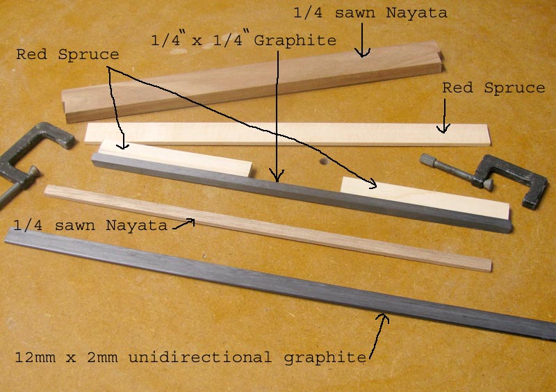
Anyhow, it was at this point that I decided I would just have to be patient and wait for an order of some 12mm x 2mm unidirectional CF strips to come from H.E. Supplies in QLD, the tip on the supplier was kindly provided by James Mc and the people at H. E. Supplies were very helpful in cutting the CF to fit into an express post bag and then getting it in the post on that same day. (Thanks James, thanks H.E. Supplies)
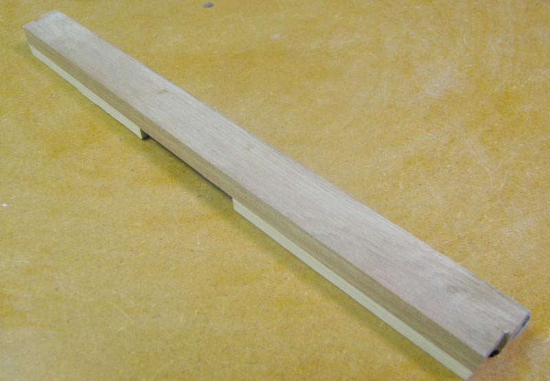
While waiting for the 2mm CF to turn up, I got to thinking about those unidirectional CF neck rods I mentioned earlier. I had a look and found that I actually had some 1/4" x 1/4" CF material. So I got out the dremel and cut-off wheel and cut the rod to length and then clamped it in place for a look.........
and the rest is history folks, the concept of the Integrated Composite Upper Transverse Beam or 'ICUT Beam' had been born
And, once the CF arrived from QLD, this is all the bloody bits 'I cut' to make it.......
These components, minus the long bit of spruce which was later glued onto the top in the normal UTB position, as per the bracing images above, were then coated with epoxy, assembled, and clamped.....
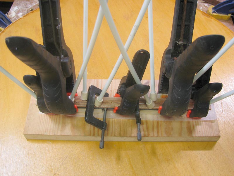
And with a clean-up the brace or beam was ready for fitting to the body of the guitar. This next image shows the beam as it will eventually sit within the body of the guitar.
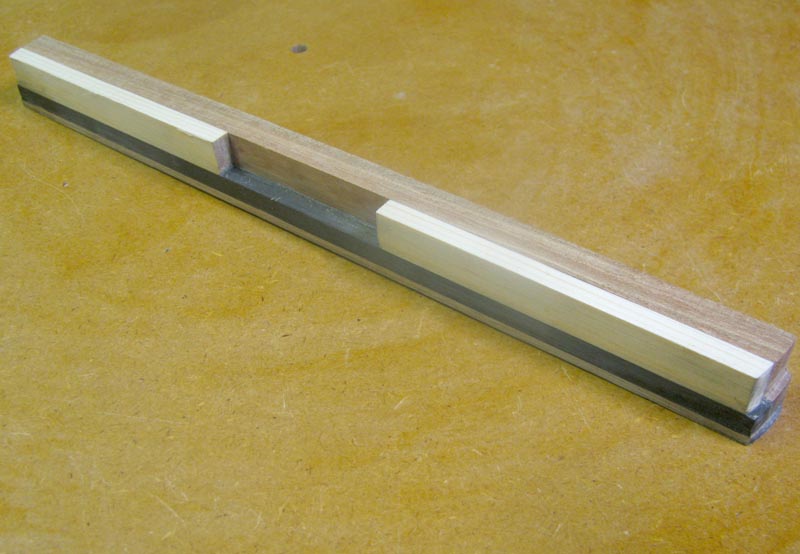
If you are wondering, the second fillet of Nayata was glued in place below the 1/4" CF rod to give an even plain to bottom to the beam. A rebate was then cut into the bottom of the beam and the 12mm x 2mm strip of unilateral CF was inlaid and glued into place.
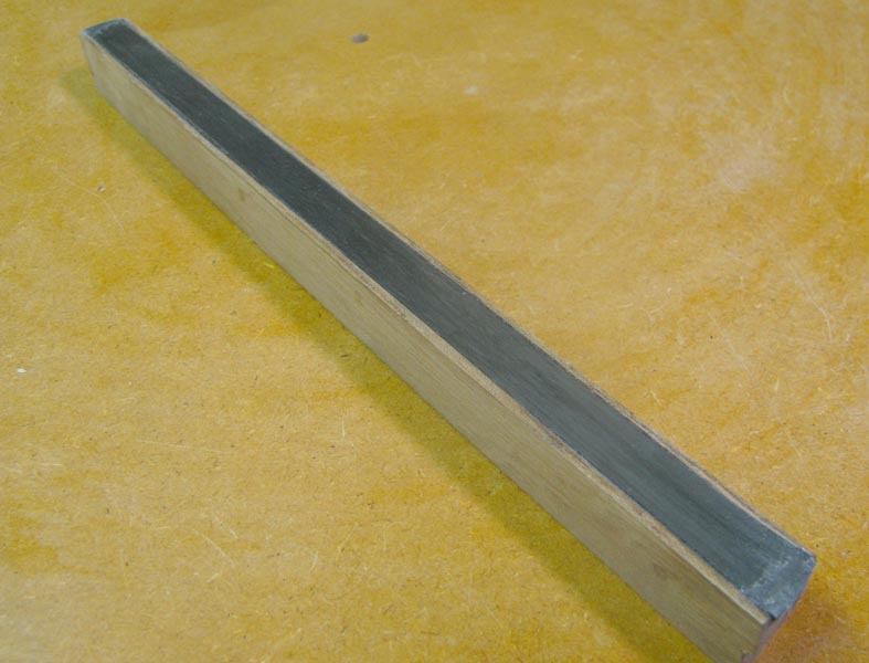
This left the back of the beam just plain wood, with very much the same appearance when viewed through the soundhole as the original UTB installed by Maton. The only difference, aside from the support brackets that would be required for the beam, would be that the ICUT beam is made from 1/4 sawn Nayata instead of Durian.
Once in position, the end of the neck tenon will travel through the neck block extension, across a small gap between the end of the neck block extension and the ICUT beam and then between the two pieces of red spruce. The back end of the neck tenon will then butt up against the strip of Nayata and the bottom 1/4" of the end of the neck tenon will rest directly upon the 1/4" CF rod.
More later.....
Coming from you I take that as a big pat on the back.
Thanks Stu,
Glad your enjoying the thread, these things are a lot of work but when I think back to how much these kind of submissions helped me along I feel more than happy to give a bit back.
Thanks for the bolts Allen
Ryeteehoe,
On to the modified UTB.....
It was around this stage of the Matey F1-11 rebuild that a call went out to my good friends here at the ANZLF for a strip of carbon fibre sheets stock to be used in a vertical aspect between two strips of wood. When I put out the request, I later found that I really knew nothing of CF other than I already had some rods intended for neck reinforcement, but no sheet. I had just assumed that pretty much any CF would work fine for what I had in mind.
You can read my call for help in THIS THREAD which, thanks to the generosity, knowledge and patience of our most learned member Jeff Highland, along with input from many other enthusiastic forum members such as Dennis Leahy, turned into a truly enlightening discussion on the use of carbon fibre as a reinforcement material.
If you read that thread, you will see that I had no sooner put out the call for some CF when John Madison, who had also kindly put a few of us from the ANZLF up in his home during Playmakers 09, had come to the rescue with an offer to send me some CF sheet stock that had been left with him by our good friend David Hurd. (Thanks again John and David)
I took John up on his kind offer (Still got the sheet thanks John
Not only that, but it also became apparent that it was far better to use this unidirectional CF laid 'horizontally' along the very 'bottom' layer of a laminated beam rather than in the vertical aspect between wooden slats which I had intended, and as I had so often seen done by other builders...(thanks again for your patience Jeff)
Anyhow, it was at this point that I decided I would just have to be patient and wait for an order of some 12mm x 2mm unidirectional CF strips to come from H.E. Supplies in QLD, the tip on the supplier was kindly provided by James Mc and the people at H. E. Supplies were very helpful in cutting the CF to fit into an express post bag and then getting it in the post on that same day. (Thanks James, thanks H.E. Supplies)
While waiting for the 2mm CF to turn up, I got to thinking about those unidirectional CF neck rods I mentioned earlier. I had a look and found that I actually had some 1/4" x 1/4" CF material. So I got out the dremel and cut-off wheel and cut the rod to length and then clamped it in place for a look.........
and the rest is history folks, the concept of the Integrated Composite Upper Transverse Beam or 'ICUT Beam' had been born
And, once the CF arrived from QLD, this is all the bloody bits 'I cut' to make it.......
These components, minus the long bit of spruce which was later glued onto the top in the normal UTB position, as per the bracing images above, were then coated with epoxy, assembled, and clamped.....
And with a clean-up the brace or beam was ready for fitting to the body of the guitar. This next image shows the beam as it will eventually sit within the body of the guitar.
If you are wondering, the second fillet of Nayata was glued in place below the 1/4" CF rod to give an even plain to bottom to the beam. A rebate was then cut into the bottom of the beam and the 12mm x 2mm strip of unilateral CF was inlaid and glued into place.
This left the back of the beam just plain wood, with very much the same appearance when viewed through the soundhole as the original UTB installed by Maton. The only difference, aside from the support brackets that would be required for the beam, would be that the ICUT beam is made from 1/4 sawn Nayata instead of Durian.
Once in position, the end of the neck tenon will travel through the neck block extension, across a small gap between the end of the neck block extension and the ICUT beam and then between the two pieces of red spruce. The back end of the neck tenon will then butt up against the strip of Nayata and the bottom 1/4" of the end of the neck tenon will rest directly upon the 1/4" CF rod.
More later.....
Last edited by Kim on Sat Aug 29, 2009 4:16 pm, edited 2 times in total.
-
John Steele
- Blackwood
- Posts: 155
- Joined: Fri Mar 06, 2009 4:58 pm
- Location: Wilson, NY. 14172
- Contact:
-
Dennis Leahy
- Blackwood
- Posts: 872
- Joined: Wed Oct 10, 2007 12:32 am
- Location: Duluth, MN, US
- Contact:
Wow, Kim, I'm betting that your ICUT beam is pretty damn strong! You could probably use it as a pry-bar to move Uluru.
Yes, that thread on CF and Jeff's patient explanation made the dimmer switch on my lightbulb go to the bright position. I'm very appreciative of that insight, so onya Kim for starting it, and to Jeff for infinite patience with me.
Kim, this is a very good, informative thread. I know it takes longer to do a thread like this than the actual work, and I sure do appreciate it!
Dennis
Another damn Yank!
Who is online
Users browsing this forum: Google and 62 guests