Build thread for first Gore SS from the plans in the book.

Talk about musical instrument construction, setup and repair.

Moderators: kiwigeo, Jeremy D

johnparchem
Blackwood
Posts: 552
Joined: Mon Jan 21, 2013 2:59 am
Location: Seattle
Contact:

Build thread for first Gore SS from the plans in the book.

Post by johnparchem » Mon Mar 17, 2014 11:36 am

I thought this might best forum to start and maintain a build thread for a Gore medium body steel string to his plan form the Build book. I will try to follow the proceedure as best I can from the book, although I can not promise I will do things in the same order, but I will at least follow the dependency graph laying out the steps.

During the next week i will be building the required jigs and body molds and what not but decided to start selecting and preparing the plates.

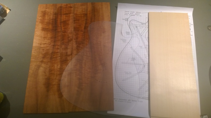
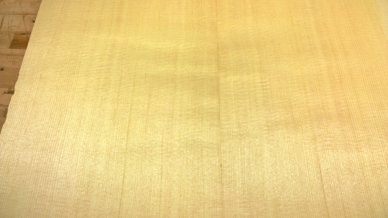
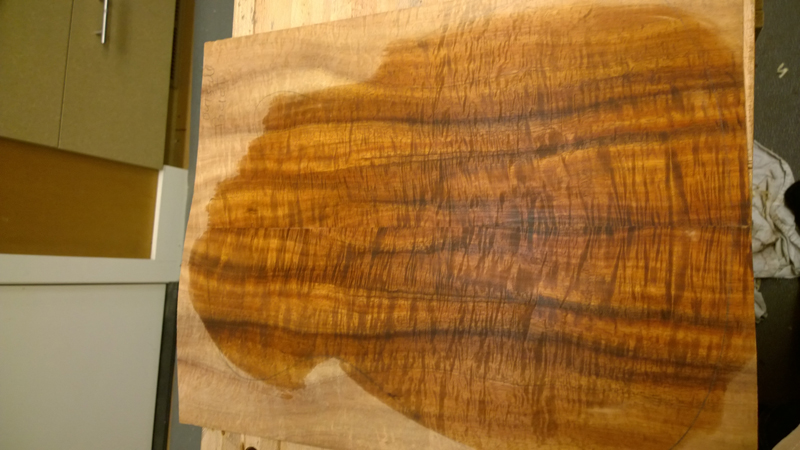
I have decided to use a Tasmanian Blackwoold set I got from Australian Tonewoods and a Lutz top I got from High Mountain Tonewood.

Image

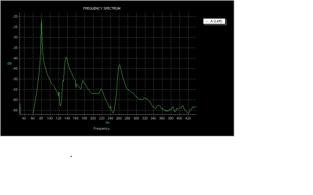
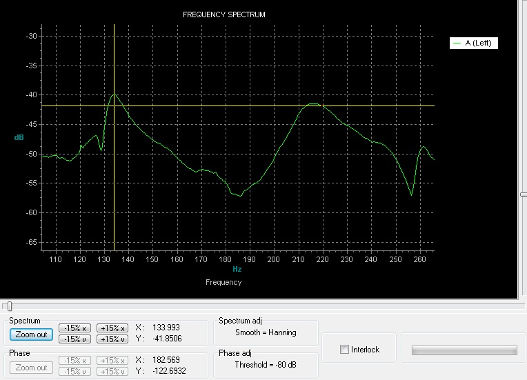
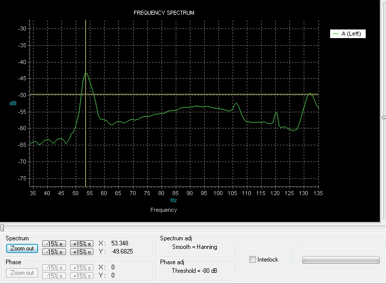
I followed section 6.2 Tap testing the panels for the top. I think I am getting good spectrum plots. I ended up with the following results

Image

Long Grain fl
Image

Cross Grain fc
Image

Twisting vibration flc
Image

More to come later.

User avatar
kiwigeo
Admin
Posts: 10675
Joined: Sat Sep 29, 2007 5:57 pm
Location: Adelaide, Sth Australia

Re: Build thread for first Gore SS from the plans in the boo

Post by kiwigeo » Mon Mar 17, 2014 12:02 pm

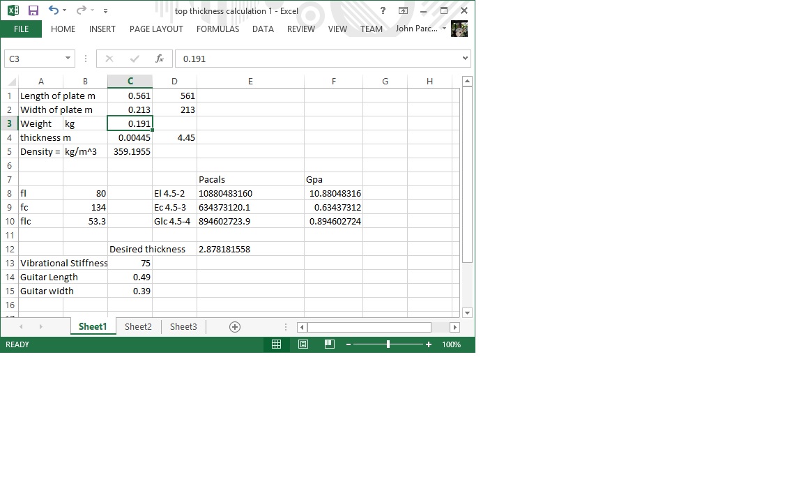
John your plate thickness calcs look ok.....I plugged same inputs into my spreadsheet and got 2.7mm as target thickness. Close enough.

Cheers Martin
Martin

johnparchem
Blackwood
Posts: 552
Joined: Mon Jan 21, 2013 2:59 am
Location: Seattle
Contact:

Re: Build thread for first Gore SS from the plans in the boo

Post by johnparchem » Tue Mar 18, 2014 4:40 am

Thanks Martin, I am not sure why there is the small difference, maybe the way I entered the formulas into excel.

Here are the thickness calculations I got for the back. I really had to thin the plate to get all of the saw marks; I ended up right at 3 mm for the tap test. The thickness basically came out to 2.8 mm, so right or wrong it is at least a normal thickness.
Attachments
back calculations.jpg
back calculations.jpg (57.09 KiB) Viewed 35549 times

johnparchem
Blackwood
Posts: 552
Joined: Mon Jan 21, 2013 2:59 am
Location: Seattle
Contact:

Re: Build thread for first Gore SS from the plans in the boo

Post by johnparchem » Tue Mar 18, 2014 5:13 am

The Design book say that 2.8 just about assures a non active back. This wood is less dense than IER by quite a bit so I suspect the above plate could be a bit thicker as the mass would still be lower than a typical rosewood plate to achieve the same vibrational stiffness.

User avatar
jjh
Myrtle
Posts: 54
Joined: Fri Jul 25, 2008 7:14 am
Location: Nr London, UK

Re: Build thread for first Gore SS from the plans in the boo

Post by jjh » Tue Mar 18, 2014 8:06 am

Really looking forward to following this build it may help me understand the books

johnparchem
Blackwood
Posts: 552
Joined: Mon Jan 21, 2013 2:59 am
Location: Seattle
Contact:

Re: Build thread for first Gore SS from the plans in the boo

Post by johnparchem » Tue Mar 18, 2014 3:02 pm

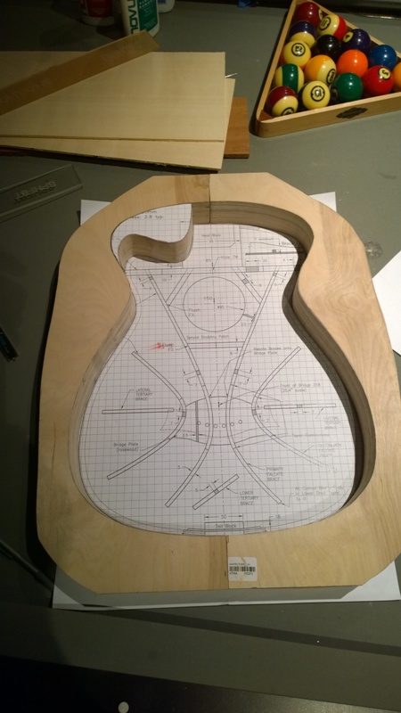
I think it will be awhile before I do the interesting work as I am working on jigs and forms. The 3 meter radius dish is throwing me for a loop, but I will find someone to make. I will probably have them make a 10 foot dish so that it is understandable. I have a 32 foot dish, so if no one complains I will pretend that it is a 10 meter dish. I mostly completed my body mold, still need to add the hardware.

Image

johnparchem
Blackwood
Posts: 552
Joined: Mon Jan 21, 2013 2:59 am
Location: Seattle
Contact:

Re: Build thread for first Gore SS from the plans in the boo

Post by johnparchem » Sat Mar 22, 2014 5:25 pm

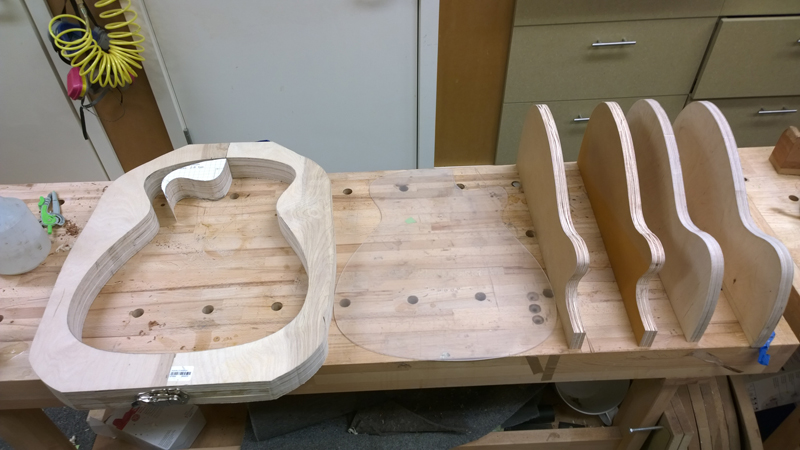
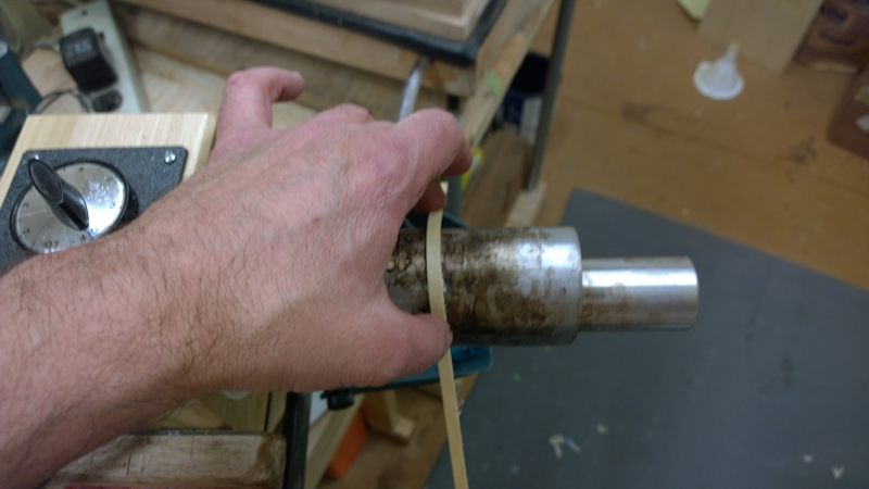
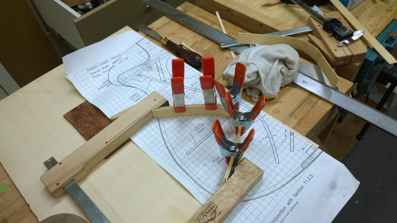
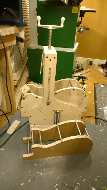
I made some progress of my bending forms. I decided to also make a cutaway form. I have a cutaway clamp on my fox style bender. I need to get some pipes to finish them off. I also need to wait for my 10 foot radish dish of that I can profiles the sides.

Image

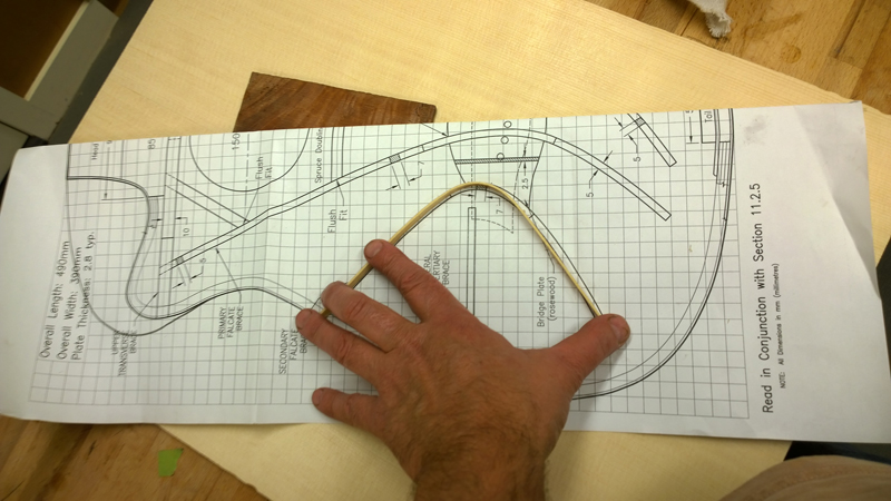
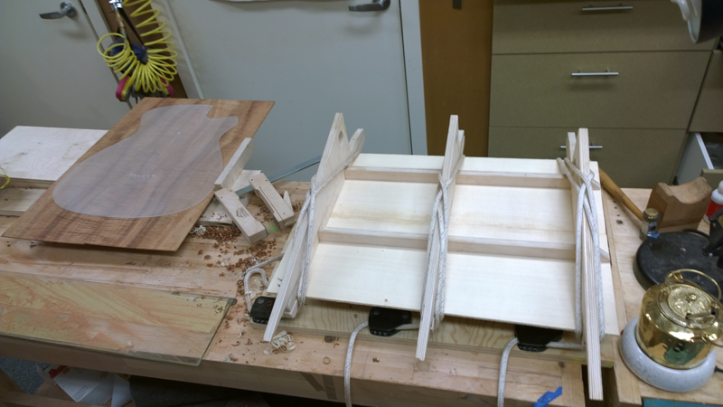
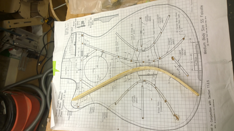
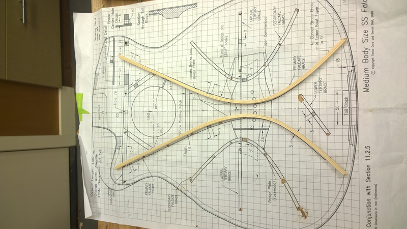
In the mean time I decided to see how it is bending spruce is for the tighter of the two falcate braces. I first tested a scrap 1.7mm strip of spruce I had. I was able to bend it no problem so I cut and thicknessed a few wider strips. I sprayed them with super soft II and bend them. I do not think it lasts very long, otherwise I will have soft braces. I will see in a week or so.

Image

Image

Image


I am really excited about the lutz top and the Australian Blackwood back and sides.

Image

Image


I tried to use hot hide glue to glue the top together I am not sure if I was fast enough as the joint was not very good. I ended up glue it with LMI white.

Image


Crafty Fox
Blackwood
Posts: 146
Joined: Sun Mar 06, 2011 3:09 pm
Location: Perth, WA

Re: Build thread for first Gore SS from the plans in the boo

Post by Crafty Fox » Sun Mar 23, 2014 7:50 pm

That Tas. Blackwood is magnificent! Looking forward to your progress. Thanks for sharing.
Ken

MattW
Myrtle
Posts: 72
Joined: Wed Apr 27, 2011 9:42 pm

Re: Build thread for first Gore SS from the plans in the boo

Post by MattW » Sun Mar 23, 2014 8:14 pm

Looking Good, the perspex template looks good. The one I made out of 3mm MDF is getting a bit scruffy around the edges

Have a look at this link for another way to make a radius dish.

http://www.kitguitarsforum.com/archives ... 79_0_6_0_C
Cheers

Matt

johnparchem
Blackwood
Posts: 552
Joined: Mon Jan 21, 2013 2:59 am
Location: Seattle
Contact:

Re: Build thread for first Gore SS from the plans in the boo

Post by johnparchem » Tue Mar 25, 2014 3:25 am

Thanks guys,

I have and I do make long radiused sanding blocks. Luckily my wife has a large format printer, so it is easy for to make arcs in a CAD program and print them as a guide. I like the dishes to serve as my work board during the project. I also leave the braced top and back pressed into their radiused dish until I am ready to close the instrument. I did think about making the 3 meter radius dish using a 3 meter length or so of stranded steel guide wire attached to my router and a beam I have on a deck that is a bit over 3 M. I thought I would attach a tent like wire setup to a router motor using a 3 inch pipe clamp. I would use the router as a plum bob to center the dish and set the height of the bit on the outside edge of the dish. Then my thought is I could happily route away. I am sure it would have made quite a mess.

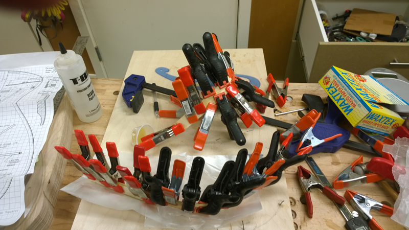
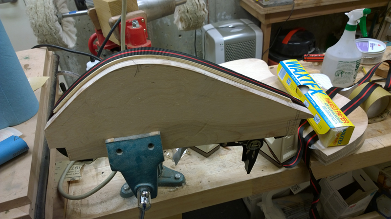
Speaking of messes I did epoxy the stack of falcate brace strips. They turned out OK. In the future if I stick to the falcate bracing I will make a couple of molds and use a band clamp.


Image

Image

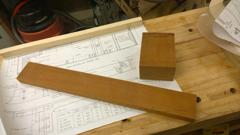
On to the neck

Image

johnparchem
Blackwood
Posts: 552
Joined: Mon Jan 21, 2013 2:59 am
Location: Seattle
Contact:

Re: Build thread for first Gore SS from the plans in the boo

Post by johnparchem » Mon Mar 31, 2014 4:09 pm

I have been working my way up toward the more interesting aspects of this guitar. Building jigs and forms is not my favorite thing and if there are templates, bending forms and molds available I will happy give the fine people who make them my business. Like the harp ukulele I made I am in the situation where I need to make the entire set of templates, molds and bending forms. Thank goodness for the copying shop, I made copies of the plans, cut them up, glued them to the plywood or Plexiglas and went to work with my band saw and sanders.

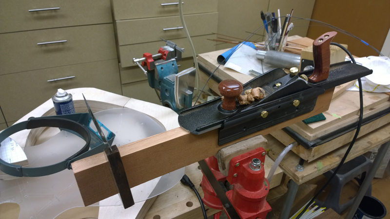
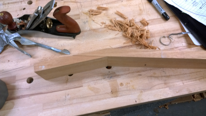
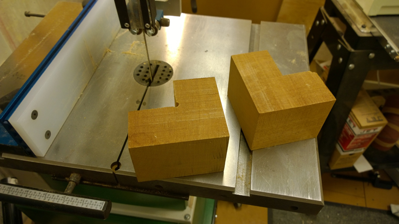
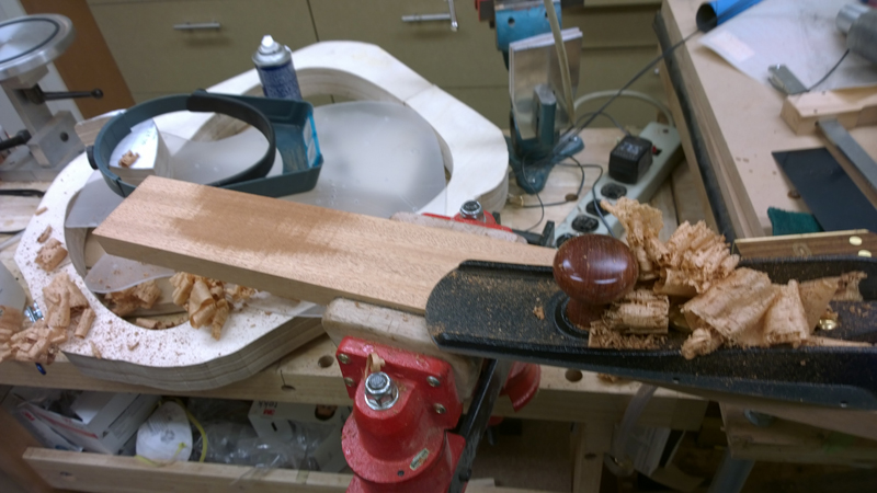
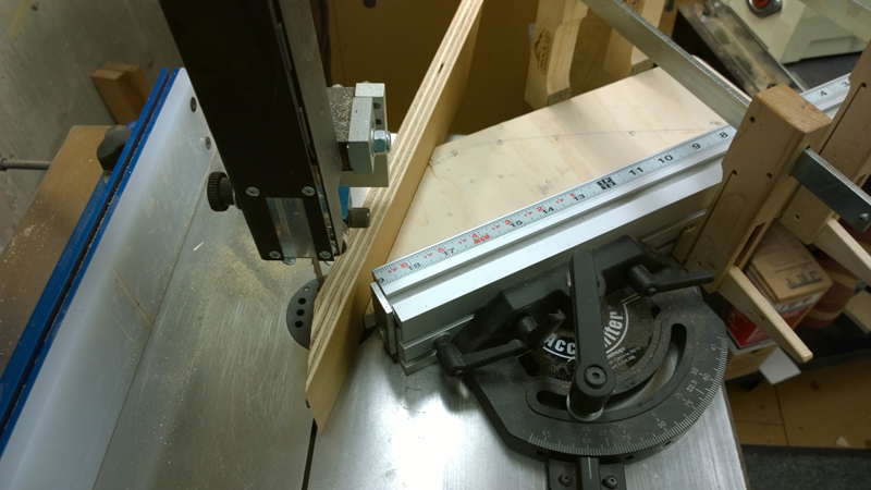
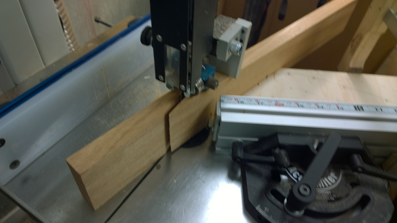
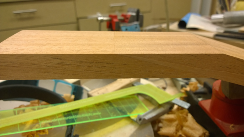
This last week I made my first scarf joint neck blank. I have been cutting necks out of single pieces of wood. I have sort of been scared of the joint as I can not cut a straight line on the band saw. Luckily my kids bought me a miter guide for my band saw. I could not cut a 15° with it but I cut some plywood at a 45 degree angle allowing to set and hold my scarf angle. It actually worked and I got a clean cut. Here are pictures of the process, including my bone headed screw up.

First I used my jointer plan to square the wood,
Image

Image

Then I cut a 45° angle to use as a guide for the miter. Just to be sure I made a test scarf cut on some scrap plywood
Image

Not sure what I was afraid of the cut when as good as it could on the bandsaw and I just need ot to do a little clean up. I lined up the cut angled pieces and clamp them with a sacrificial piece of MDF, and planed the gluing surface of the joints clean and flat
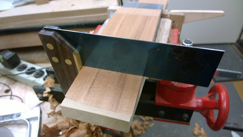
Image

Image

Image

I used my shooting board and some clamps to hold the joint in place and really glued it with some heavy duty clamps.
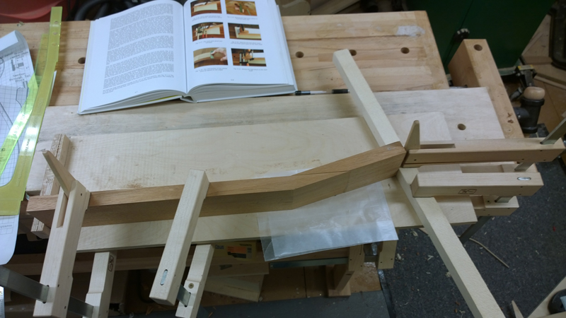
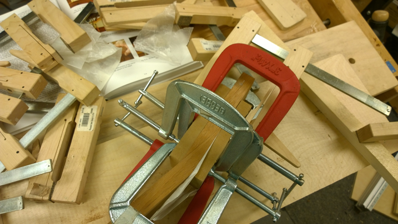
Image

Image

Image

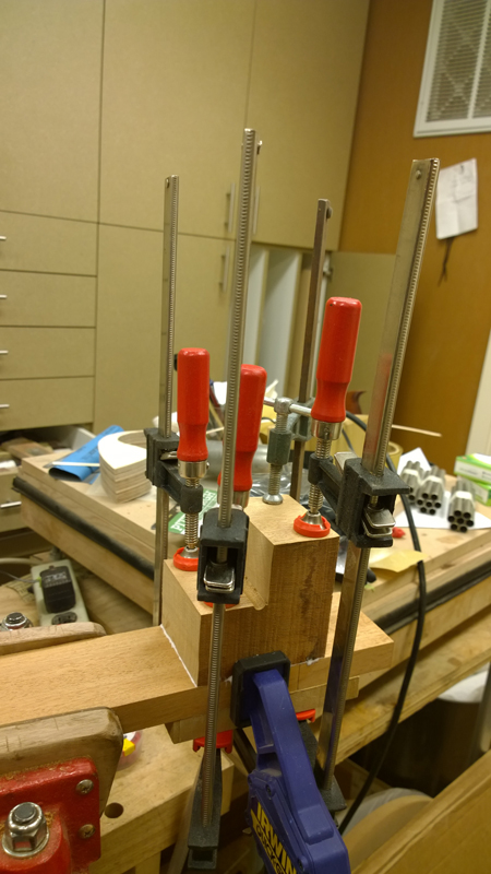
I had a big block for the heal so I cut it into two heel blanks. Here again I planed the surfaces flat and used some real clamps to glue the heel on the neck.
Image

Image

Image

Image

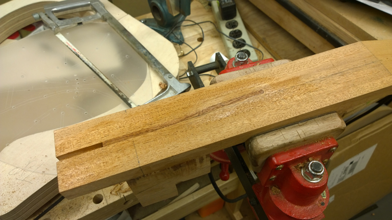
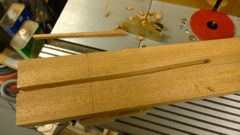
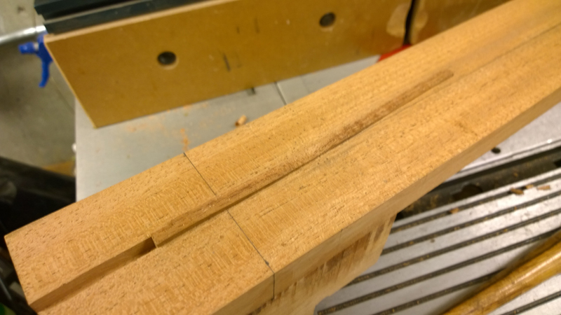
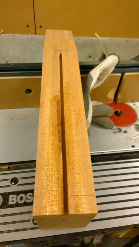
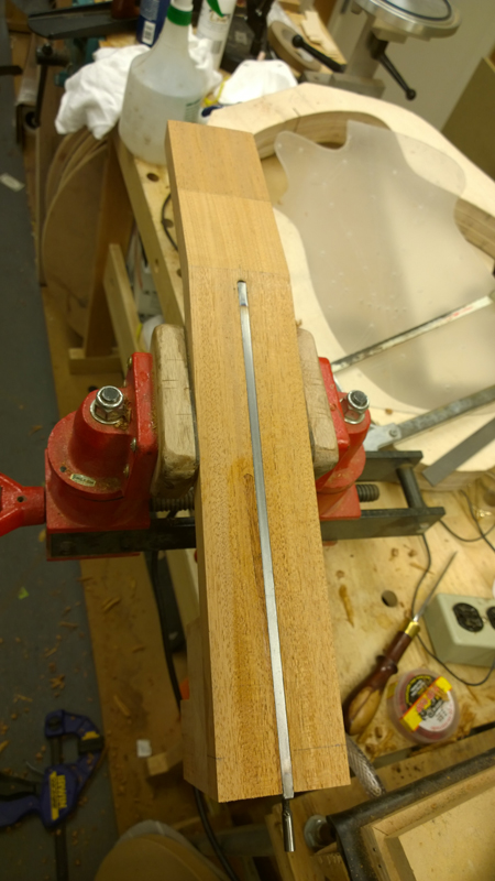
Here is where the bone head maneuver came in to play. I very carefully set up the router table for a truss rod slot right up the center of the neck blank. Then proceed to start the route before tightening the router table fence. Oh well. I cut a strip of mahogany planed it and shaped it to fit in the miss-cut slot. It fit in so nicely that I just wicked in some CA. I reset the table a made a proper slot. No one will see this fix, unless they are changing the fret board in the future for a repair.
Image

Image

Image

Image

Image.

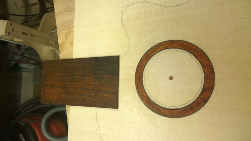
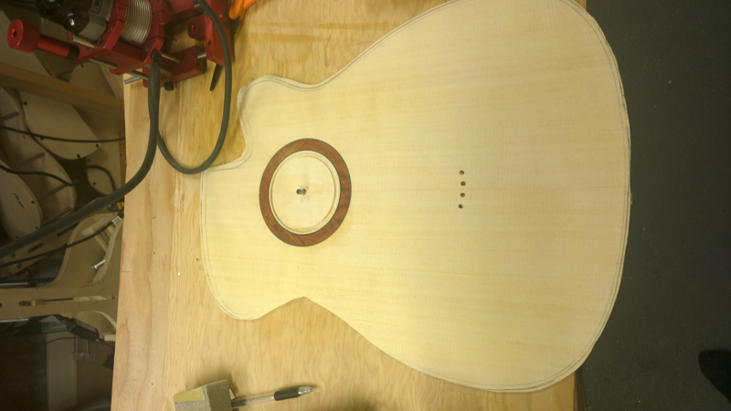
I also installed an extra amboyna rosette I made as an option for a previous guitar.

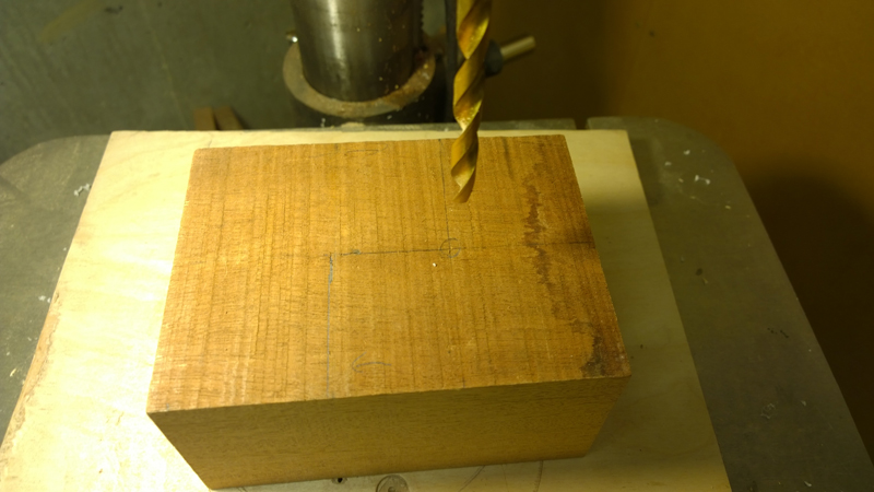
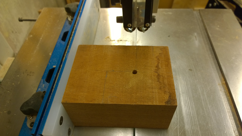
To insure proper bridge and sound hole alignment, and given that I need to drill the peg holes early in the bracing process. I used the template to drill some of the peg holes and the center of the rosette.
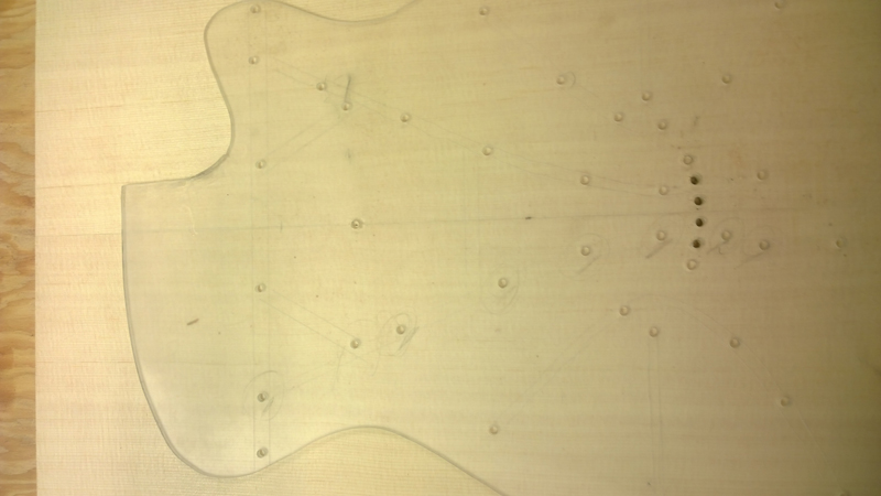
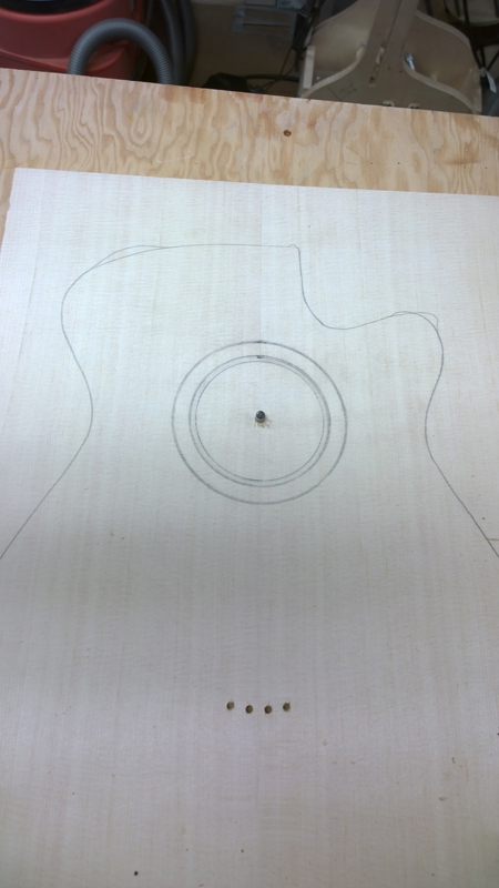
Image

Image

I did not do any fancy measurements I just used the router and it fine adjustment to sneak up of the slot I need for the rosette and a couple of thin bwb purflings.
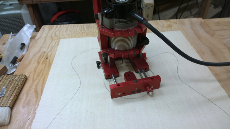
Image

All and all uneventful

Image

I routed the sound hole such that it should be close to dropping out when the top is the correct thickness.
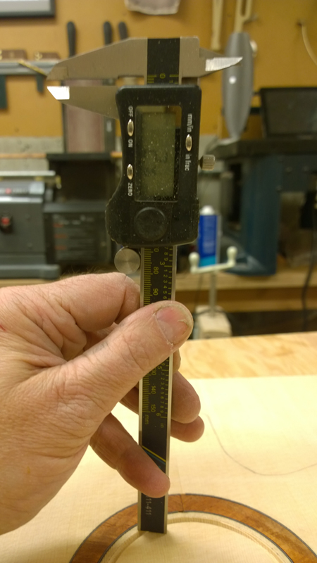
Image

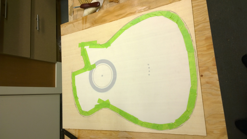
Once very close to the proper thickness I made a 3 mill mylar to cover for the top to protect it during bracing.
Image

Image

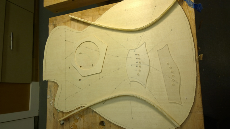
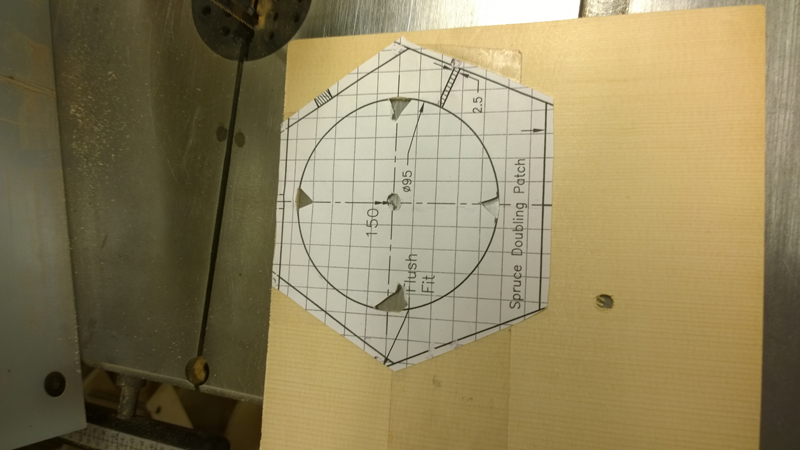
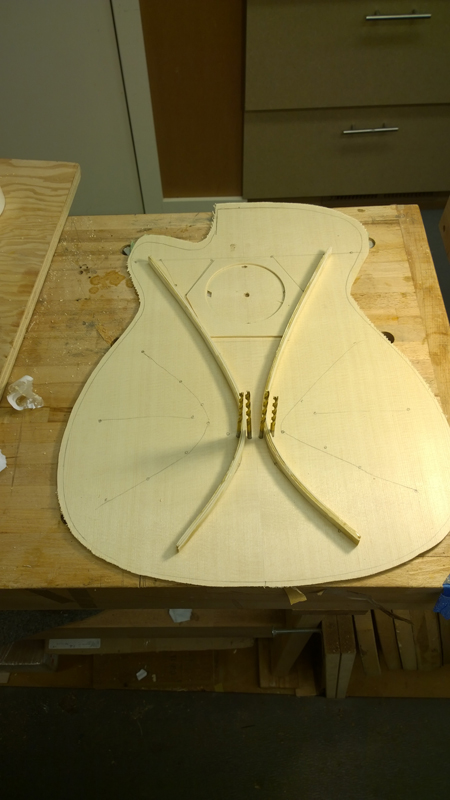
I spent the rest of the weekend preparing to do the top bracing. The last photo shows why I need to drill the peg holes so early; the main braces passes between two peg holes.
Image

Image

Image

Image

User avatar
kiwigeo
Admin
Posts: 10675
Joined: Sat Sep 29, 2007 5:57 pm
Location: Adelaide, Sth Australia

Re: Build thread for first Gore SS from the plans in the boo

Post by kiwigeo » Tue Apr 01, 2014 10:29 pm

Looking good John and a nice save on that truss rod slot.

From the photos it looks like you took out a fair bit of material on what I assume was the first pass over the router table. I do a pass with the cutter just kissing the wood to check everything is lined up and it also serves to check for things like loose fences etc.
Martin

User avatar
charangohabsburg
Blackwood
Posts: 1818
Joined: Sat Oct 16, 2010 1:25 am
Location: Switzerland

Re: Build thread for first Gore SS from the plans in the boo

Post by charangohabsburg » Wed Apr 02, 2014 12:30 am

kiwigeo wrote:I plugged same inputs into my spreadsheet and got 2.7mm as target thickness.
johnparchem wrote:Thanks Martin, I am not sure why there is the small difference, maybe the way I entered the formulas into excel.

Here are the thickness calculations I got for the back. I really had to thin the plate to get all of the saw marks; I ended up right at 3 mm for the tap test. The thickness basically came out to 2.8 mm, so right or wrong it is at least a normal thickness.
Hi John, I'm a bit late with this, but hopefully not too late, and hopefully it is not a false alarm! I also plugged you data in my spreadsheet and get 2.72 for the top, and then... 2.52 for the back. Your results for density, El, Ec and Glc are exactly the same as those my spreadsheet spits out, so the mistake must sit in the programming of Equ. 4.5-7, either in my and Martin's, or in your spreadsheet.

T0 obtain your top thickness result I have to adjust the vibrational stiffness parameter to 79.5 (instead of 75), and for the back I have to adjust it to 61.5 (instead of 55).

Cheers,
Markus

To be stupid is like to be dead. Oneself will not be aware of it.
It's only the others who suffer.

johnparchem
Blackwood
Posts: 552
Joined: Mon Jan 21, 2013 2:59 am
Location: Seattle
Contact:

Re: Build thread for first Gore SS from the plans in the boo

Post by johnparchem » Wed Apr 02, 2014 1:21 am

Thank you, for the check. Not too late at all. I will go back and re-code equation Equ. 4.5-7. it really help knowing that density, El, Ec and Glc are exactly the same to isolate the problem. I did go over the equation again and it looks correct as far as I can see. Here is the equation I have that matches spreadsheets in my earlier post. I am really heavy on parentheses not trusting order of operation.

=((0.95977*C13*(C14^2)*SQRT(C5))/SQRT(E8+((C14/C15)^4*E9)+((C14/C15)^2*((0.02857*E8)+(1.12*F10)))))*1000
Attachments
back 2.jpg

User avatar
charangohabsburg
Blackwood
Posts: 1818
Joined: Sat Oct 16, 2010 1:25 am
Location: Switzerland

Re: Build thread for first Gore SS from the plans in the boo

Post by charangohabsburg » Wed Apr 02, 2014 2:41 am

Yes there are some unnecessary parenthesis, but this should not hurt. The rest looks fine too. You could try to use (xyz)^0.5 instead of SQRT(xyz).

P.S.
...and then double check with a pocket calculator, pencil and a piece of paper, which is what I had done when setting up my spreadsheet. :wink:
Markus

To be stupid is like to be dead. Oneself will not be aware of it.
It's only the others who suffer.

johnparchem
Blackwood
Posts: 552
Joined: Mon Jan 21, 2013 2:59 am
Location: Seattle
Contact:

Re: Build thread for first Gore SS from the plans in the boo

Post by johnparchem » Wed Apr 02, 2014 3:32 am

Thanks, I tried (xyx)^.5 and I tried separate calculations for all of the products in the denominator.
I think a calculator will be my next go.

johnparchem
Blackwood
Posts: 552
Joined: Mon Jan 21, 2013 2:59 am
Location: Seattle
Contact:

Re: Build thread for first Gore SS from the plans in the boo

Post by johnparchem » Wed Apr 02, 2014 6:38 am

Thanks for the help, taking the time to run the numbers. It turned out I was using Gpa instead of Pascals for Glc.

((0.95977*C13*(C14^2)*SQRT(C5))/SQRT(E8+((C14/C15)^4*E9)+((C14/C15)^2*((0.02857*E8)+(1.12*F10)))))*1000

When I did the partial products for the denominator I noticed a product too small to make a difference.
Now I get 2.71 mm for the top and 2.61 for the back!

Now I can get an active back.

User avatar
charangohabsburg
Blackwood
Posts: 1818
Joined: Sat Oct 16, 2010 1:25 am
Location: Switzerland

Re: Build thread for first Gore SS from the plans in the boo

Post by charangohabsburg » Wed Apr 02, 2014 8:42 am

That one seems to be fixed. Well done! 8)

I hadn't looked up which data (cells) you run through the formula. A very common mistake to use a wrong cell though, a simple typo I guess.
The idea to use ^0.5 instead of sqrt came because I remember having gotten strange results with Excel's SQRT function handling very large and very small numbers two decades ago or so, which was when I stopped using it. I even forgot it existed!
johnparchem wrote:Now I get 2.71 mm for the top and 2.61 for the back!
Is 2.61 for the back another typo?
I get 2.71706 for your top and 2.51852 for your back (with the data you provided in the beginning, of course).
Markus

To be stupid is like to be dead. Oneself will not be aware of it.
It's only the others who suffer.

johnparchem
Blackwood
Posts: 552
Joined: Mon Jan 21, 2013 2:59 am
Location: Seattle
Contact:

Re: Build thread for first Gore SS from the plans in the boo

Post by johnparchem » Wed Apr 02, 2014 9:36 am

charangohabsburg wrote:That one seems to be fixed. Well done! 8)

I hadn't looked up which data (cells) you run through the formula. A very common mistake to use a wrong cell though, a simple typo I guess.
The idea to use ^0.5 instead of sqrt came because I remember having gotten strange results with Excel's SQRT function handling very large and very small numbers two decades ago or so, which was when I stopped using it. I even forgot it existed!
johnparchem wrote:Now I get 2.71 mm for the top and 2.61 for the back!
Is 2.61 for the back another typo?
I get 2.71706 for your top and 2.51852 for your back (with the data you provided in the beginning, of course).
Hmm I get 2.71705951 for the top so we are at a very insignificant rounding difference

Just cut and pasted my fixed top equation into my back spreadsheet that had my fix but with other changes and I got 2.5185. Now I will call it good!

Thanks again,

John

User avatar
charangohabsburg
Blackwood
Posts: 1818
Joined: Sat Oct 16, 2010 1:25 am
Location: Switzerland

Re: Build thread for first Gore SS from the plans in the boo

Post by charangohabsburg » Wed Apr 02, 2014 10:09 am

johnparchem wrote: [...] and I got 2.5185. Now I will call it good!
...or if it is wrong, at least we made the same mistakes! :mrgreen:

Cheers,
Markus

To be stupid is like to be dead. Oneself will not be aware of it.
It's only the others who suffer.

johnparchem
Blackwood
Posts: 552
Joined: Mon Jan 21, 2013 2:59 am
Location: Seattle
Contact:

Re: Build thread for first Gore SS from the plans in the boo

Post by johnparchem » Thu Apr 03, 2014 10:36 am

Thanks to Markus, see above I found I had a small error in my equation for plate thickness. My error basically took the diagonal stiffness measurement out of the equation give me a slightly thicker plate.

So now my top plate target is 2.7 mm and my back (I want an active back) number is 2.5 mm. It did not make much difference on the top but it did make nearly a 10% difference on the back.

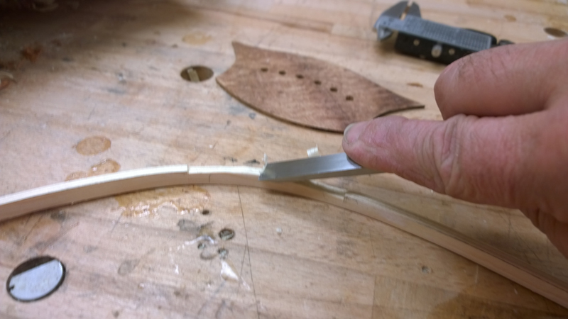
While preparing my primary braces for gluing I planed one lower then I the target height. I finished one brace, was starting on the other and got distracted and planed down the finished brace. Oh well. I got to try a new way to laminate these braces. I sliced and thickness three long 25mm by 1.7 mm german spruce strips. As before I bend them with my iron and a mist of water to close to the correct bend. This time though I used the inside cut out material from my mold to make a brace mold and used a strap clamp to pull the strips together. This technique was in the Gore\Gilet Build book.

Image

I waxed the mold and strap with paste wax but ultimately I also used wax paper when I laminated the strips with System 3 structural epoxy. The result was a perfectly shaped brace with no spring back.

Image

I cut the 25 mm braces into two braces and used a plane to take them down to just a bit more than 7mm. The 7 mm is my target height for the brace before I shape them.

Image

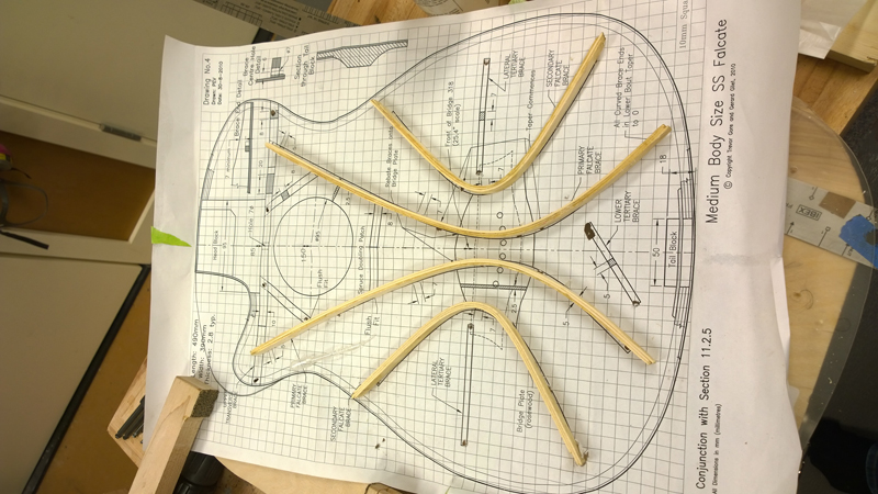
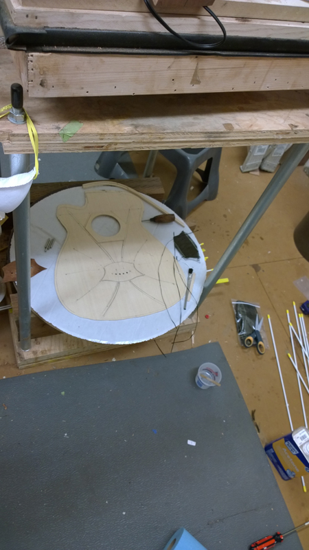
I laid out the braces and the bridge plate on the top in my modified 32' Radius dish I drilled four index holes in the dish so that I can use them to index the top, the bridge plate and the braces during glue up.

Image

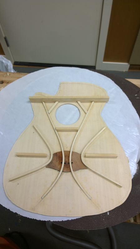
With every thing in place I marked where I need rebates in the primary braces. Also I tested out using thinned Teflon strips to center the braces between the peg holes.
Image

Image

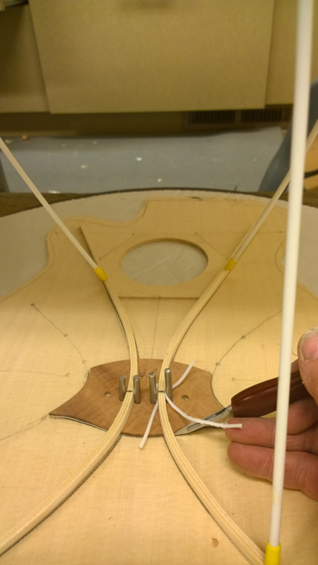
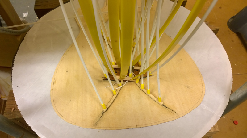
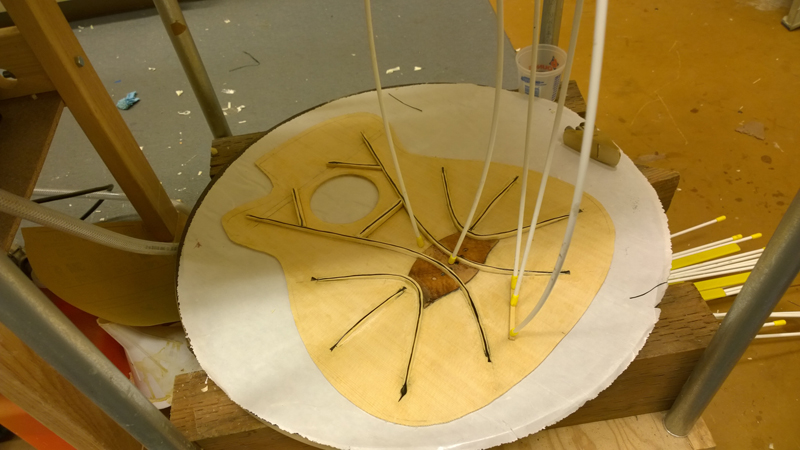
No excuses now I needed to take epoxy to my relatively clean top. I got every thing I was going to need close to my go bar deck. This included a piece of carbon fabric I cut for under the bridge plate and three (one extra) fibers or yarns from the weave of the carbon fiber for under the braces.
Image

I mixed up a cup of West System 105\106 epoxy for the glue up. I used a brush to wet the top along the brace path and the area marked for the bridge plate. I applied epoxy to the strips just enough to wet them and laid them down in the center of the brace locations.
Image

Sorry for the lack of pictures I has epoxy on my gloves. I also applied epoxy to the carbon fabric shaped for the bridge plate and put that down. I used a pointer to push open the fabric and inserted my 3/16 pins I am using for indexing. I pushed the bridge plate and followed with the two braces. Go-bars on every thing, my spacer strips between the braces and the index pins . So now I either have a complete mess or tomorrow I will have a top with epoxied primary braces.

Image

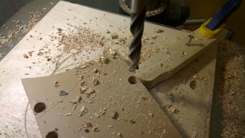
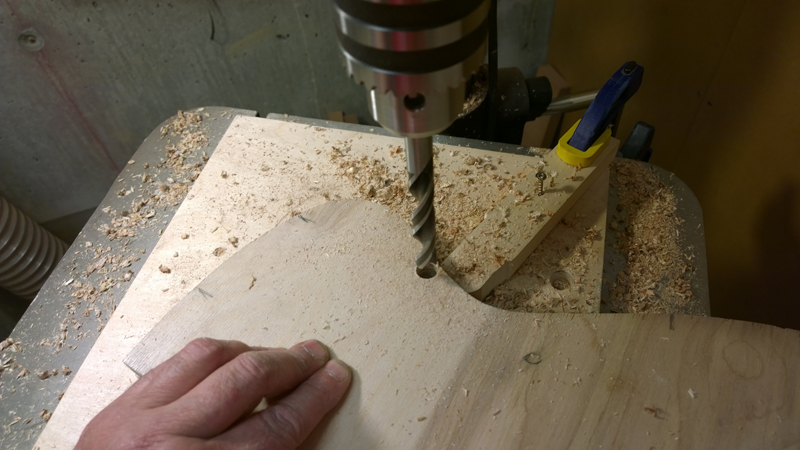
While waiting for the epoxy to cure. I finished my two side bending molds. I again used what is probably a common technique but one I got from the build book to drill the holes close to edge of my bending form.

Image

Image

Image

johnparchem
Blackwood
Posts: 552
Joined: Mon Jan 21, 2013 2:59 am
Location: Seattle
Contact:

Re: Build thread for first Gore SS from the plans in the boo

Post by johnparchem » Sat Apr 05, 2014 5:35 am

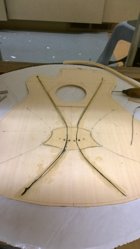
Moving on, I waited to the following morning and remove the go-bars. The brace seems to be epoxied on well and carbon stayed under brace. I can say that carbon fiber hardware with epoxy make wicked splinters. Luckily I have my magnifying glasses and some good tweezers.

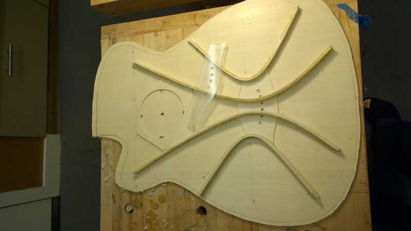
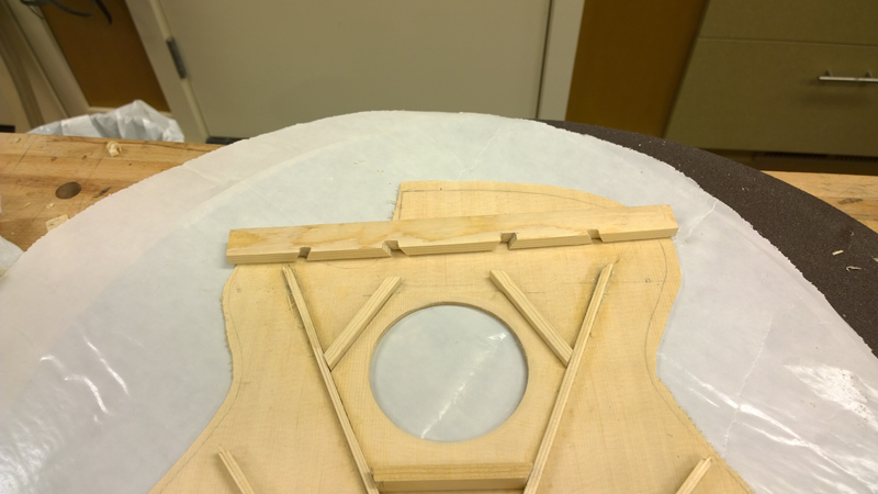
I cut the remaining braces and prepared for the next epoxy glue up. The primary falcate braces and the sound hole braces inlet into the upper transverse brace. While I will not glue the upper transverse until I have all of the other braces glued on. I still cut the rebates.

Image

Image

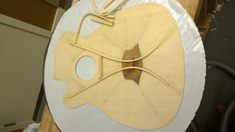
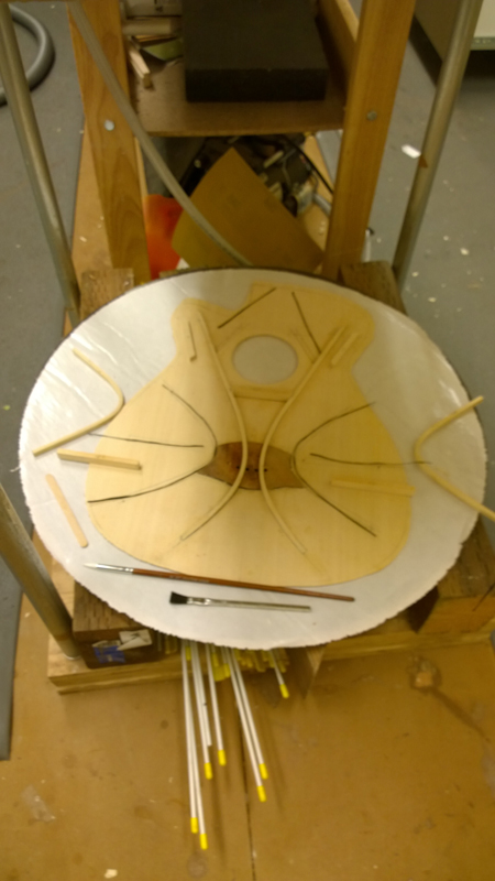
I traced all of the braces so I will know where to put the carbon fiber.

Image

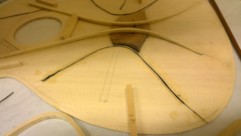
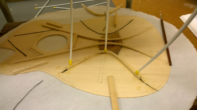
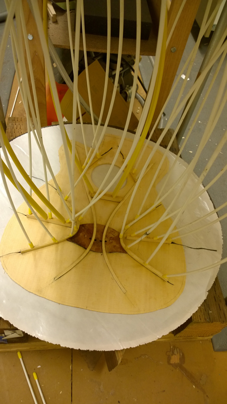
Then back to the go-bar deck. I have gotten pretty neat with with LMI glue but I am a mess with this epoxy. Maybe if I did not use my gloved fingers as squeegees for the fibers I would be a bit neater. While gluing down one of the falcate braces I did need to lift it, remove excess epoxy and relay it as a bit of the carbon squirted out. The was no problem gluing all the braces seen in the working time of the epoxy.

Image

Image

Image

Image

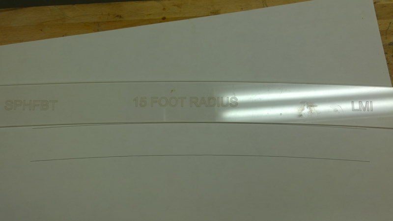
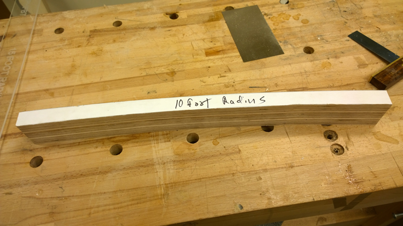
Having to wait for the epoxy I started to think about the back and thought it would help to have a 10 foot radius stick. No need for a shipwright compass as my wife is a designer with a large format printer at home. I made two arcs and used more scrap from my body mold to make the radius block. In one of the pictures you can see the difference between a 15' and a 10' radius. The plans actually calls out a 3 meter radius dish but the 10' is close; 118" vs 120" My dish is schedule to arrive Wednesday. I want to use the dish to make an accurate side profile before bending the sides.

Image

Image

User avatar
colburge
Blackwood
Posts: 344
Joined: Fri Mar 02, 2012 11:14 am
Location: Upper Caboolture

Re: Build thread for first Gore SS from the plans in the boo

Post by colburge » Sat Apr 05, 2014 6:55 am

Thanks for documenting this, it really is a lot of work to build and take decent photos. I've had the books for 12 months now and I am just waiting for winter to arrive and the humidity to decrease before I start on my next build, so I find it interesting to watch your build, even though the books document exactly what you have done.

Cheers

Col

johnparchem
Blackwood
Posts: 552
Joined: Mon Jan 21, 2013 2:59 am
Location: Seattle
Contact:

Re: Build thread for first Gore SS from the plans in the boo

Post by johnparchem » Sun Apr 06, 2014 11:00 am

The build book has really good picture of everything I am doing and much better descriptions. I guess if anything this blog shows a relatively novice builder going through the procedure.

I carved down all the braces I have epoxied down. The falcate braces are about 7 mm around the bridge and simply taper to about 5 mm near the upper transverse brace. On the tail end of the guitar the braces taper down to zero. I was looking at my two side braces and they really looked clunky. Whoops they were 7 mm wide instead of 5 mm. A sharp chisel took care of that error no problem. I also noticed I forgot the lower tertiary brace. no problem as I still have three epoxy sessions. One to put carbon fiber on all of the finished braces. One to glue down the upper transverse brace and lastly to top the upper transverse brace with carbon fiber.

Here is my top with the carbon fiber on the finished braces and gluing down the forgotten brace. I go back and look at the pictures in the book and Trevor's epoxy work with the carbon sure looks cleaner than mine.

Image

Next I need to build a gluing caul for the UTB. This design knocks a bit of curve to make the neck angle work out. The book list out a procedure to make it. I think I will draw it in my cad program and print it out.

Post Reply

Who is online

Users browsing this forum: Google and 54 guests